
Vibration detection method based on laser wavefront coding technique

A coding technology, vibration detection technology, applied in measuring devices, using wave/particle radiation, measuring ultrasonic/sonic/infrasonic waves, etc. Detect problems such as application range, inconvenient integration of piezoelectric vibration sensors, etc., to achieve the effect of easy expansion of functions, high reliability, and easy integration

Active Publication Date: 2016-01-20
上海微鸢电子科技有限公司
View PDF5 Cites 6 Cited by
  • Summary
  • Abstract
  • Description
  • Claims
  • Application Information

AI Technical Summary

Problems solved by technology

There is a vibration detection method in the prior art, see US patent, patent name: Piezoelectricvibrationssensor, inventor: OrtenBirger, patent number: US7656524B2, patent authorization time: May 06, 2008, translated into Chinese name: a piezoelectric vibration Sensors, this prior technology has certain characteristics, but there are essential deficiencies: 1) Vibration detection based on the piezoelectric principle, based on piezoelectric materials to make vibration sensors, it is difficult to achieve long-distance vibration telemetry, and the anti-interference ability is not strong; 2) The detected object and its environment will affect the piezoelectric vibration sensing process and affect the accuracy, sensitivity, and reliability of the detection results; 3) Piezoelectric materials and vibration sensors made of piezoelectric materials have intrinsic frequency characteristics, The frequency response behavior of vibration information detection is limited, which not only affects the amount of vibration detection information and detection application range; 4) The construction of vibration detection system is complicated, the function is difficult to expand, and the piezoelectric vibration sensor is not easy to integrate

Method used


Image

  • Vibration detection method based on laser wavefront coding technique

Examples


Embodiment Construction

[0027] The present invention will be further described below in conjunction with drawings and embodiments.

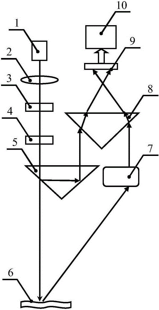
[0028] Such as figure 1 As shown, an embodiment of a vibration detection method based on laser wavefront coding technology, based on the laser astigmatism field phase interference behavior, combined with the principle of laser wavefront coding, using dynamic wavefront polarization and phase coding, after coding, the light field splits and returns The reference beam, and the forward test beam, the test beam is projected onto the vibrating object to be detected, and the light field of the speckle part passes through the defocused imaging component to form an information beam carrying coded information and vibration information of the object, and the information beam and the reference beam Overlapping interference forms an interference field. The photoelectric sensor is set in the interference area to realize photoelectric transmission. The vibration analysis unit processe...


PUM


Abstract

The invention relates to a vibration detection method based on the laser wavefront coding technique. In the prior art, the high-performance and non-destructive telemetry of the vibration information cannot be realized. According to the technical scheme of the invention, the method is designed based on the phase-interference behavior and the laser wavefront coding principle of a laser astigmatism field, wherein the dynamic wavefront polarization and the phase encoding are conducted. After the coding process, the light beam of a light field is separated into a feedback reference beam and a forward test beam. The test beam is projected onto a to-be-detected vibration object. An information beam is formed in the part of the light field that is provided with speckle spots by means of an out-of-focus imaging component. Through the overlapping and intersecting process of the information beam and the reference beam, an interference field is formed. A photoelectric sensor is arranged in an interference region, so that the photoelectric conversion of the interference information is realized. A vibration analyzing unit is used for analyzing the vibration information of a detection region through processing the above information. The method has the advantages of high sensitivity, high reliability, non-contact detection, non-destructive telemetry, strong anti-interference capability, flexible frequency characteristics, large amount of information, easy system construction, wide application range, easy function expansion, convenient integration, flexible construction and the like.

Description

technical field [0001] The invention belongs to the field of optoelectronic engineering, and relates to a vibration detection method, especially a vibration detection method based on laser wavefront coding technology, which is mainly used in vibration monitoring, environmental perception, Internet of Things, process control, advanced manufacturing, voice collection, Vibration detection in the fields of acoustic diagnosis, noise analysis, environmental monitoring, etc. Background technique [0002] Vibration detection widely exists in vibration monitoring, environmental perception, Internet of Things, process control, advanced manufacturing, voice acquisition, acoustic diagnosis, noise analysis, environmental monitoring and other fields, and the demand for vibration detection is getting higher and higher. There is a vibration detection method in the prior art, see US patent, patent name: Piezoelectricvibrationssensor, inventor: OrtenBirger, patent number: US7656524B2, patent ...

Claims


Application Information

Patent Timeline
IPC IPC(8): G01H9/00
Inventor 高秀敏苏文秀辛青逯鑫淼
Owner 上海微鸢电子科技有限公司
Learn More