A transient shock wave temperature measurement system and method

A temperature measurement, shock wave technology

Active Publication Date: 2017-11-21
CHINA INSTITUTE OF ATOMIC ENERGY
View PDF4 Cites 0 Cited by
  • Summary
  • Abstract
  • Description
  • Claims
  • Application Information

AI Technical Summary

Problems solved by technology

It uses a streak camera to scan the shock wave luminescence, and determines the radiation intensity according to the output digital signal of the CCD of the streak camera (CCD is Charge-coupled Device, the full name in Chinese is: charge-coupled device, also called image controller). The optical measurement system is relatively Complicated, the calibration of the whole system is quite cumbersome, and it is easy to introduce measurement errors

Method used


Image

  • A transient shock wave temperature measurement system and method
  • A transient shock wave temperature measurement system and method

Examples


Embodiment 1

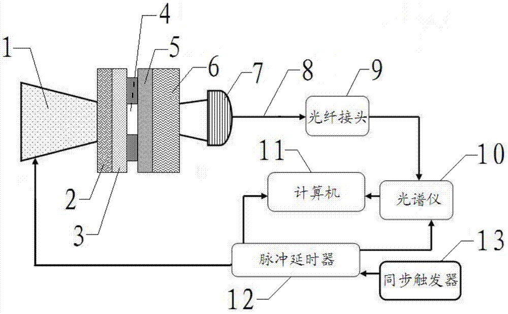
[0034] Such as figure 1 As shown, the shock wave of the measured temperature is generated by the transient shock wave generating device, which includes a laser driver 1, a flyer target 3, a vacuum chamber 4, a metal target 5, and a LiF window 6 connected in sequence, wherein the flyer An ablation layer 2 is provided on the side of the target 3 close to the laser driver 1 .

[0035] A kind of transient shock wave temperature measurement system provided by the present invention comprises the signal collector 7 arranged outside the LiF window 6 of the transient shock wave generating device (the side away from the metal target 5), connected to the signal collector 7 through an optical fiber 8 Optical fiber joint 9, connect the spectrometer 10 of optical fiber joint 9, connect the computer 11 of spectrometer 10, respectively connect the pulse delay device 12 of laser driver 1 in spectrometer 10, computer 11, transient shock wave generation device, connect pulse delay device 12 Syn...

Embodiment 2

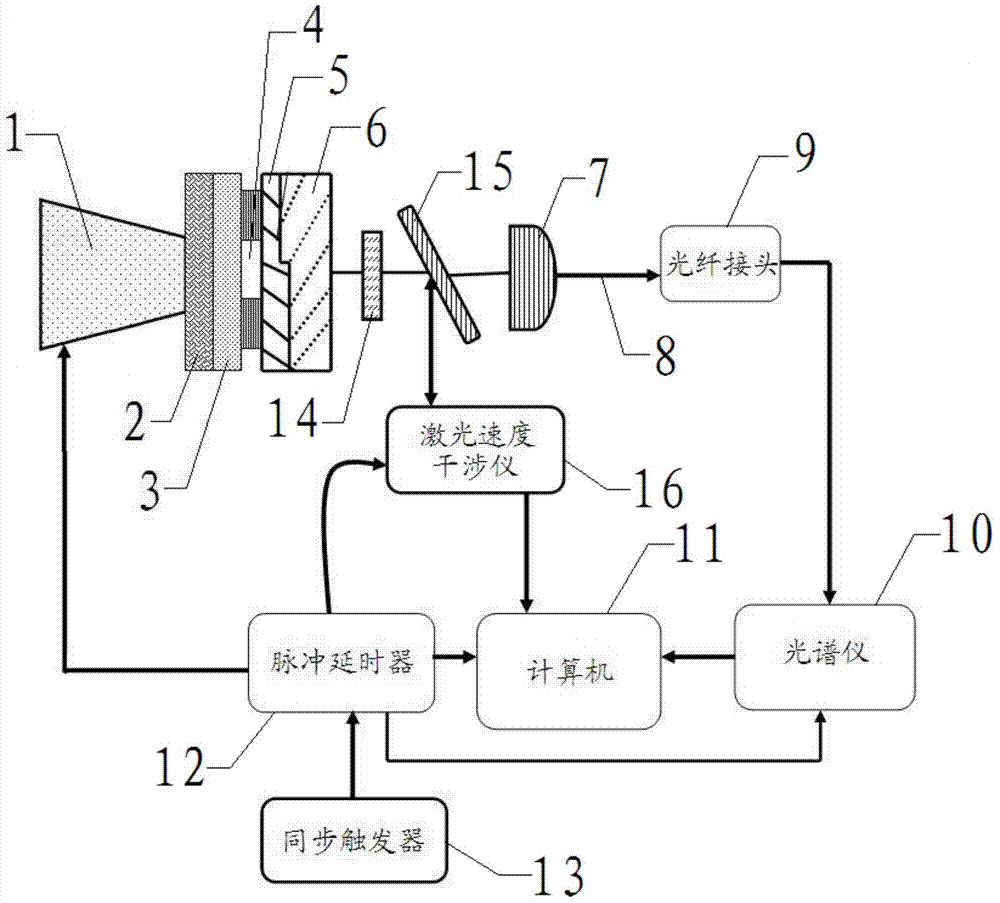
[0040] Transient shock wave temperature measurement system with laser velocity interferometer (also can be considered as "complete equation of state experimental diagnosis system for transient shock wave temperature measurement")

[0041] Such as figure 2 As shown, the transient shock wave temperature measurement system provided by the present invention, in conjunction with the laser velocity interferometer (in this embodiment, the laser velocity interferometer 16 is an imaging laser velocity interferometer VISAR), can simultaneously obtain the kinematic parameters and thermodynamic parameters of the material. Parameter (the described material is the inner material used to generate shock waves and emit thermal radiation light arranged in the transient shock wave generating device, i.e. metal target 5), thereby obtaining a complete equation of state, the specific scheme is:

[0042] The shock wave of the measured temperature is generated by a transient shock wave generating de...


PUM


Abstract

The invention belongs to the technical field of spectral temperature measurement, and in particular relates to a transient shock wave temperature measurement system. Traditional radiation pyrometers cannot measure the temperature of laser-driven shock waves with a duration of about 10 ns. Existing pyrometers suitable for measuring the temperature of laser-driven shock waves have complex structures, cumbersome debugging, and heavy calibration workload; using the measurement system provided by the present invention, It includes a signal collector arranged outside the transient shock wave generating device, an optical fiber connector connected to the signal collector through an optical fiber, a spectrometer connected to the optical fiber connector, a computer connected to the spectrometer, respectively connected to the spectrometer, computer, The pulse delayer of the transient shock wave generating device is connected to the synchronous trigger of the pulse delayer; the temperature of the laser-driven shock wave with a duration of about 10ns can be tested, the structure is simple, the debugging is convenient, and the measurement accuracy is high.

Description

technical field [0001] The invention belongs to the technical field of spectral temperature measurement, and in particular relates to a transient shock wave temperature measurement system and method. Background technique [0002] The shock wave temperature measurement method in the traditional (light gas cannon) dynamic high-pressure loading equation of state study is mainly the "radiation pyrometer method". On the order of hundreds of microseconds. However, the thickness of the high-speed flyer and target driven by the laser is on the order of microns, and the duration of the shock wave is only about 10 ns. Therefore, the traditional radiation pyrometer cannot be used for the study of the laser-driven high-voltage equation of state. In 2007, J.E.Miller [1] proposed and developed a scanning optical pyrometer system (streaked optical pyrometer system—SOP) for measuring laser-driven shock wave temperature. It uses a streak camera to scan the shock wave luminescence, and dete...

Claims


Application Information

Patent Timeline
Patent Type & Authority Patents(China)
IPC IPC(8): G01K13/00G01J5/00
Inventor 李业军王钊田宝贤张品亮殷倩
Owner CHINA INSTITUTE OF ATOMIC ENERGY
Why Eureka
Try Eureka