Microstrip reflective array unit loaded with cross slot on ground, and reflective array antenna

A cross-shaped, reflective array technology, applied to antennas, electrical components, circuits, etc., can solve problems such as limiting the scope of application

Inactive Publication Date: 2016-01-20
NAT SPACE SCI CENT CAS
View PDF2 Cites 15 Cited by
  • Summary
  • Abstract
  • Description
  • Claims
  • Application Information

AI Technical Summary

Problems solved by technology

[0004] In 2003, M.R.Chaharmir et al. proposed an aperture-coupled reflection unit loaded with an inline slot on the ground. Compared with the traditional form of adjusting the reflection phase by changing the size of the unit, the reflection unit of this structure improves the antenna bandwidth to a certain extent. , but the reflection unit can only work in the single-line polarization perpendicular to the length direction of the slit, which limits its application range to a certain extent

Method used


Image

  • Microstrip reflective array unit loaded with cross slot on ground, and reflective array antenna
  • Microstrip reflective array unit loaded with cross slot on ground, and reflective array antenna
  • Microstrip reflective array unit loaded with cross slot on ground, and reflective array antenna

Examples


Embodiment 1

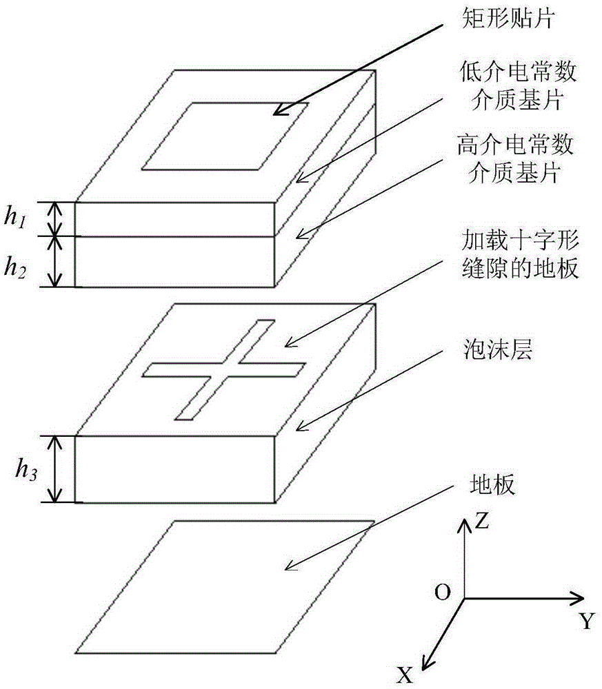
[0031] In this embodiment, what the low dielectric constant dielectric substrate adopts is the plate material of Rogers (Rogers) 5880, and its dielectric constant is 2.2; What the high dielectric constant dielectric substrate adopts is silicon nitrate (siliconnitrate) material, and its dielectric constant is 2.2. The electrical constant is 7; the length and width of the rectangular patch are equal, and the gap width in both directions is the same; the length and width of the entire unit plane are 13mm.

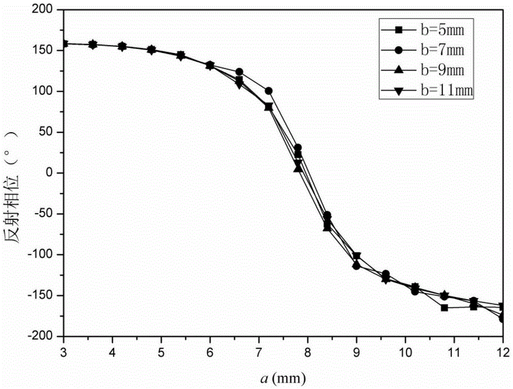
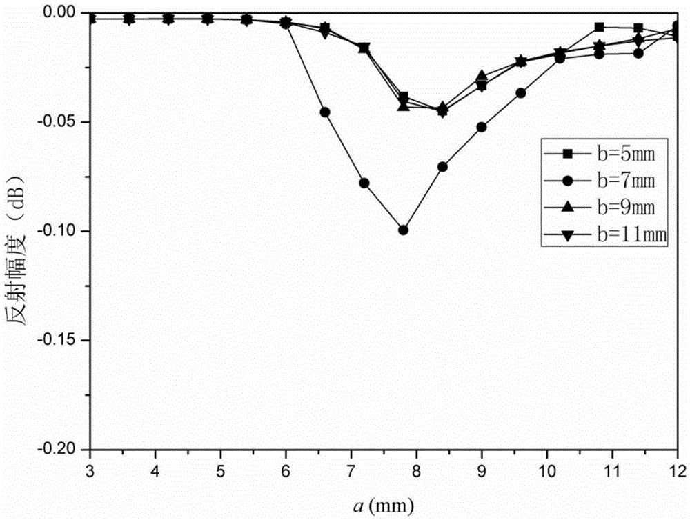
[0032] Such as figure 2 As shown, the unit is modeled and simulated using the high-frequency electromagnetic simulation software HFSS, and the curve of the reflection phase changing with the length of the gap is obtained. When the slot length in the y direction is different, the variation curves of the unit reflection phase with the slot length in the x direction are small, indicating that the ground-loaded cross-shaped slot dual-polarized microstrip reflectarray unit is inde...

Embodiment 2

[0040] In this embodiment, the feeding form of the antenna is positive feed, the focal diameter ratio F / D=0.8, and the distance from the phase of the feed source to the center of the array is 93.6 mm.

[0041] The antenna can reflect the linearly polarized feed source incident wave into a circularly polarized reflected wave. When the polarization direction of the linearly polarized feed source is the direction of the angle bisector of the angle formed by the x axis and the y axis, the incident The waves on the reflective array can be decomposed into linearly polarized waves in the x-direction and y-direction. Independently adjust the length of the unit gap in the x direction and y direction of each unit, so that the reflection phase in the x direction is ahead (or behind) the reflection phase in the y direction by 90°, so that the linearly polarized feed incident wave is reflected by the reflection array Afterwards, a right-handed (or left-handed) reflected wave is obtained. ...


PUM


Abstract

The invention provides a microstrip reflective array unit loaded with a cross slot on the ground. The microstrip reflective array unit comprises a patch, a low-dielectric constant dielectric substrate, a high-dielectric constant dielectric substrate, a floor loaded with a cross slot, a foam layer and a floor, wherein the floor loaded with the cross slot is a metal flat plate opened with the cross slot at the middle, the foam layer is a honeycomb flat plate made of foam material or paper, and all adjacent layers are in close contact. Further, the invention also provides a microstrip reflective antenna. The antenna comprises a feeding source and a microstrip reflective array, wherein the feeding source is a pyramidal horn antenna, the microstrip reflective array comprises a plurality of microstrip reflective array units loaded with the cross slots on the ground, which are transversely, longitudinally and uniformly arranged. The unit loaded with the cross slot, provided by the invention, can work in two polarization directions perpendicular to each other, and different polarizations are completely independent to one another. The reflective array antenna has the performance of line-polarized wave conversion.

Description

technical field [0001] The invention belongs to the technical field of antennas, in particular to a microstrip reflection array unit and a reflection array antenna loaded with cross-shaped slots on the ground. Background technique [0002] With the rapid development of radar, satellite communication, and space detection technologies, the demand for large-aperture high-gain antennas is increasing. Traditional high-gain antennas mainly include parabolic antennas or array antennas, but both have shortcomings. Although the parabolic antenna has high gain and wide operating frequency range, it has the disadvantages of being bulky, difficult to process, and difficult to install, especially at high frequencies. Although the array antenna is small in size, flexible in scanning mode, and large in scanning range, it has disadvantages such as low gain, large loss, complex control circuit, and expensive active components loaded. These shortcomings limit the application of the above two...

Claims


Application Information

Patent Timeline
Patent Type & Authority Applications(China)
IPC IPC(8): H01Q15/14H01Q15/24H01Q13/02H01Q19/10
Inventor 薛飞王宏建
Owner NAT SPACE SCI CENT CAS
Why Eureka
Try Eureka