On-chip microfluidic processing of particles

A particle and fluid communication technology, applied in laboratory containers, gas/liquid distribution and storage, instruments, etc., can solve problems such as height variability

Active Publication Date: 2016-01-20
GPB SCI INC +2
View PDF31 Cites 13 Cited by
  • Summary
  • Abstract
  • Description
  • Claims
  • Application Information

AI Technical Summary

Problems solved by technology

Since, these steps are done manually, the results can be highly variable

Method used


Image

  • On-chip microfluidic processing of particles
  • On-chip microfluidic processing of particles
  • On-chip microfluidic processing of particles

Examples


Embodiment 8

[0454] Example 8 describes the use of an on-chip cleaning system.

[0455] In some cases, the size-based separation methods described herein do not use centrifugation and / or sedimentation. In some cases, the size-based separation methods described herein use centrifugation or sedimentation.

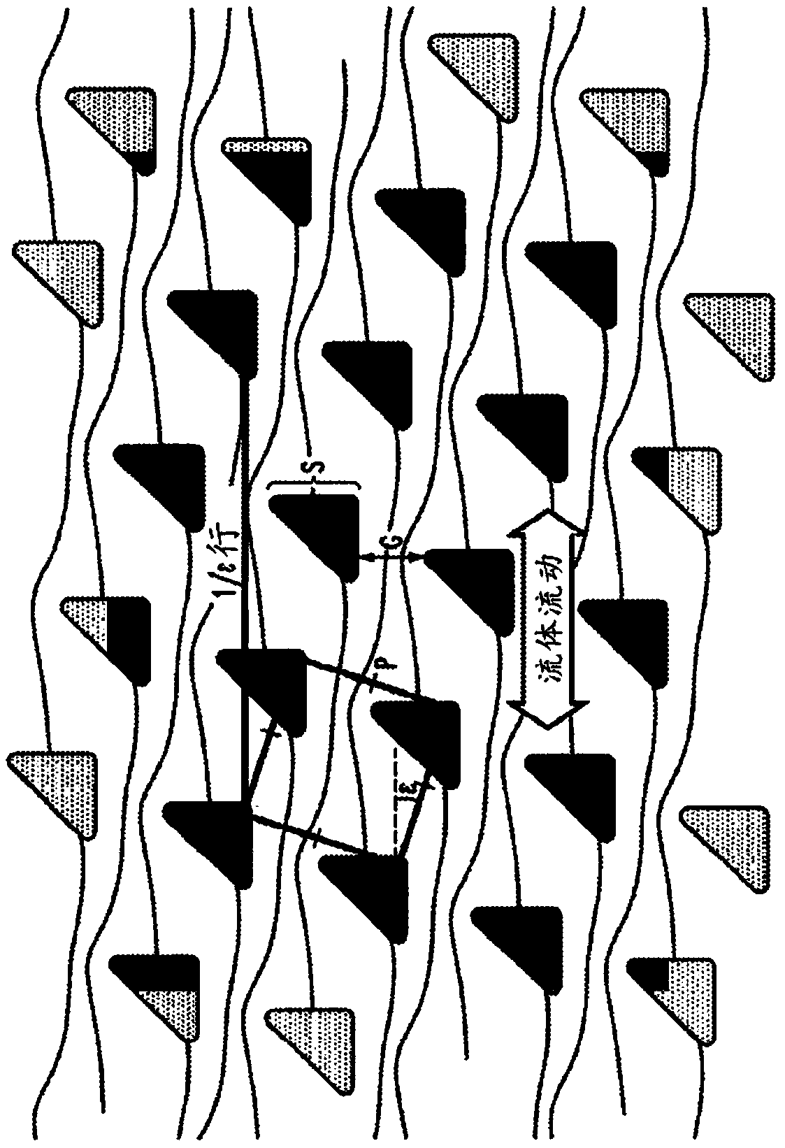
[0456] (w) cone angle

[0457] The obstacles or posts may be cylindrical. In some cases, obstacles on the device are not perfectly cylindrical. The obstacles or at least 50% of the obstacles in the array may have Taper angles of 1.5°, 1°, 0.5°, 0.4°, 0.3°, 0.2° or 0.1°. Obstacles may have a cone angle of 0°. The obstacles, or at least 50% of the obstacles in the array, may have a range of about 0.1° to about 1°, about 1° to about 2°, about 2° to about 3°, about 3° to about 4°, or about 1° to about 4° cone angle.

[0458] H. Materials of Construction and Surface Chemistry

[0459] In some embodiments, the device is fabricated by heat molding PMMA and / or polycarbonate. Thermoplasti...

Embodiment 1

[0649] Example 1: Manufacture

[0650] Chips are fabricated using highly anisotropic deep reactive ion etching (DRIE) in crystalline silicon polished substrates using a "Bosch" process that cycles between etch and sidewall passivation steps, so the pillar side The walls are only ~1° from vertical. Optical lithography defines the pattern. Through-substrate vias are micromachined to support fluid loading / unloading from the backside, which mate with plastic fixtures with connectors for input source and output collection. Chips were pretreated with triblock copolymer F108 (2 g / l) to reduce cell adhesion. Tuning chip design parameters (eg, critical size for bouncing behavior) for high yield.

Embodiment 2

[0651] Example 2: Operation

[0652] Cell surface antigens targeting multiple leukocyte differentiation (i.e., CD45 / CD14 / 15 (to determine single granulocyte type count), CD3 / 4 / 8 (to count common T lymphocyte subsets), CD19 / 56 / 14 (to identify B lymphocytes and NK cells), CD45 / CD235a / CD71 (to identify any contaminating erythroid cells)) and incubation with viability dyes ("immunostaining") Leukocytes from 0.1ml-1ml red blood cell lysed whole blood (optionally diluted with buffer (calcium and magnesium free PBS containing 1% BSA and 4mM EDTA) and optionally spiked with leukemic cells) . This is done routinely (ie, off-chip). Cells are then washed and concentrated to ~1-10 million cells / mL using a DLD chip designed to move leukocytes and leukemia cells from an initial stream of input cell suspension containing fluorescent monoclonal antibodies to Outflow of fresh buffer against the chip wall ( Figure 17B ).

[0653] The method can recover >90% of the input leukocytes and ...


PUM

PropertyMeasurementUnit
diameteraaaaaaaaaa
volumeaaaaaaaaaa
depthaaaaaaaaaa

Abstract

A microfluidic device comprises: a channel extending from a plurality of inlets to a plurality of outlets, wherein the channel is bounded by a first wall and a second wall opposite from the first wall; and an array of obstacles disposed within the channel configured to deflect particles in a sample comprising the particles toward the second wall when the particles are flowed from the inlets to the outlets. The particles are inputted into at least one of the plurality of inlets and are deflected through a series of parallel flow streams flowing from the plurality of inlets to the plurality of outlets while being deflected toward the second wall, wherein streams in the parallel flows comprise a reagent. Microfluidic devices and methods greatly improve cell quality, streamline workflows, and lower costs. Applications include research and clinical diagnostics in cancer, infectious disease, and inflammatory disease, among other disease areas.

Description

[0001] cross reference [0002] This application claims U.S. Provisional Patent Application No. 61 / 939,044, filed February 12, 2014, U.S. Provisional Patent Application No. 61 / 939,070, filed February 12, 2014, and U.S. Provisional Patent Application No. 61 / 939,070, filed March 15, 2013. The benefit of patent application Ser. No. 61 / 800,222, the entire contents of which are hereby incorporated by reference. [0003] Federal Government Sponsored Research Statement [0004] This invention was made with US Government support under Contract No. 1R41CA174121-01 to the National Institutes of Health (NIH). Background technique [0005] Current methods for sample preparation of leukocytes prior to multiparametric analysis via flow cytometry are tedious, a manual process that requires expert operators and results in loss and damage of cells. Multiparameter flow cytometry, or atomic mass spectrometry, is an increasingly powerful technique widely used in research and clinical diagnos...

Claims


Application Information

Patent Timeline
Patent Type & Authority Applications(China)
IPC IPC(8): C40B30/10F16K1/06F16L55/10F17D3/01
CPCB01L3/502753G01N30/6095B01L3/502776B01L2200/0652B01L2300/0816B01L2300/0864B01L2300/0867G01N30/6069G01N15/1484G01N2015/1481G01N2015/149G01N2015/1493
Inventor 迈克尔·格里森姆柯特·I·希文詹姆斯·C·斯特姆罗伯特·H·奥斯汀约瑟夫·迪席尔瓦陈昱
Owner GPB SCI INC
Why Eureka
Try Eureka