Automatic water taking and irrigation device on road near water area

A technology for irrigation devices and transmission devices, applied in water supply devices, irrigation pipes, machines/engines, etc., to achieve the effects of prolonging the service life, protecting the vehicle from breaking, and protecting the safety of the vehicle

Inactive Publication Date: 2016-01-27
祝珺 +14
View PDF6 Cites 0 Cited by
  • Summary
  • Abstract
  • Description
  • Claims
  • Application Information

AI Technical Summary

Problems solved by technology

The device has a simple structure, can realize automatic irrigation and drainage, does not need personnel to guard, is easy to operate, low in cost, and easy to be popularized and used. In addition, it can realize the accumulation of rainwater. This method uses the buoyancy system to collect water sources, and the degree of automation is relatively high, but still rely on the use of some electronic components

Method used


Image

  • Automatic water taking and irrigation device on road near water area

Examples


Embodiment Construction

[0031] The preferred technical solutions of the present invention will be described in detail below in conjunction with the accompanying drawings.

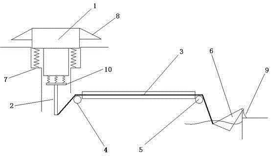
[0032] As shown in the figure, the automatic water intake and irrigation device on the road near the water area of ​​the present invention includes a pressure transmission device installed underground on the country road and a water intake and irrigation device near the river, and the pressure transmission device and the water intake and irrigation device cooperate with each other. , using the pressure of vehicles passing by to guide the water in the water area into the planting area;

[0033] The pressure transmission device includes a lower pressure plug 1 and a lower pressure rod 2. First, a through hole must be set on the road surface. The lower pressure plug 1 is arranged on the road surface with a through hole. Rebound mechanism, the rebound mechanism is used to rebound the lower pressure plug 1 upwards, the lower part of th...


PUM


Abstract

The invention discloses an automatic water taking and irrigation device on a road near a water area. The device comprises a pressure transmission device arranged on the underground of the country road and a water taking and irrigation device body arranged near the riverway; the pressure transmission device comprises a downwards pressing plug and a downwards pressing rod; the downwards pressing plug descends under rolling compaction of a vehicle to drive the downwards pressing rod to move downwards; the water taking and irrigation device body comprises a hauling cable, a first idler wheel, a second idler wheel and a water containing tank; one end of the hauling cable is connected with the lower end of the downwards pressing rod; the other end of the hauling cable is connected with the water containing tank; the water containing tank is located in the riverway to contain water; the water containing tank upwards lifts under traction of the hauling cable to guide water into an irrigation canal. Compared with the prior art, the pressure transmission device is used for stretching by using pressure of passing vehicles as a power source; the water taking and irrigation device body is used for pulling the water containing tank through the power source to scoop water inside the river to the canal of a near bank for irrigation, so that on the one hand, energy is saved for irrigating the cropland, and on the other hand, vehicles running on the country road can slow down to run on the road, and pedestrian safety is ensured.

Description

technical field [0001] The invention relates to an automatic irrigation device, in particular to an automatic water-taking irrigation device on roads near water areas. Background technique [0002] Modern rural planting technology is already very advanced, and there are various ways of water supply and irrigation in farmland, and the working methods are generally relatively simple. The work will consume a certain amount of energy, or the input of human and material resources in the early stage. [0003] For example, the automatic well irrigation system with application number 201310560803.8 is mainly composed of a control box, a soil moisture sensor, a remote pressure gauge, a butterfly valve, a check valve, a submersible pump, and a liquid level sensor. The control box controls the entire irrigation system, and the soil moisture sensor The signal to be worked is transmitted to the control box by detecting the soil humidity, and the control box controls the start and stop o...

Claims


Application Information

Patent Timeline
IPC IPC(8): E02B13/00E03B5/00F04B17/06
Inventor 胡晓荣俞娟胡瑜
Owner 祝珺
Why Eureka
Try Eureka