
Passive solar energy wall

A solar and passive technology, applied in the direction of walls, heating methods, building components, etc., can solve the problem of low heat exchange rate and achieve the effect of environmental protection indoor thermal environment

Active Publication Date: 2016-01-27
TIANJIN CHENGJIAN UNIV
View PDF9 Cites 15 Cited by
  • Summary
  • Abstract
  • Description
  • Claims
  • Application Information

AI Technical Summary

Problems solved by technology

Application number: 201220379614.1 discloses an energy-storage solar energy combined with a modular split-type phase-change house energy-saving system, including an inner room and an energy-storage air duct system. The inner room includes a front thermal storage wall, a rear thermal storage wall, a left thermal storage wall and Enclosed by the right thermal storage wall, the front thermal storage wall is connected with the energy storage air duct system through the damper; the energy storage air duct system includes the front wall, the rear wall, the left wall, and the right wall, and the front wall is surrounded by transparent The back wall, the left wall, and the right wall are made of heat-insulating panels; the passive wall in the prior art emphasizes the structure of the heat storage wall, and an insulation layer needs to be set on the heat storage wall, and its low heat exchange rate is the biggest problem

Method used


Image

  • Passive solar energy wall
  • Passive solar energy wall
  • Passive solar energy wall

Examples


Embodiment

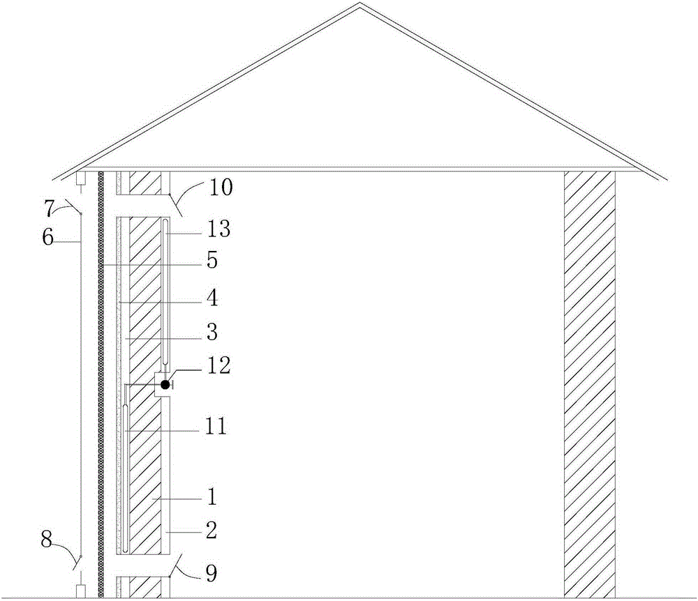
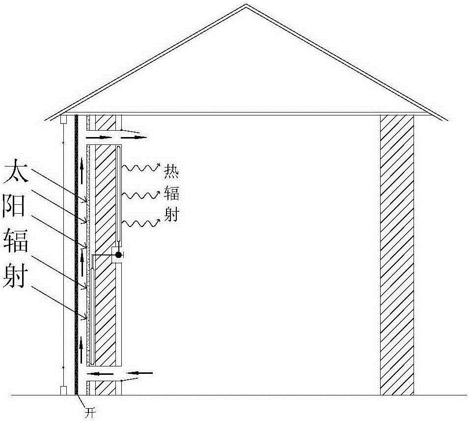
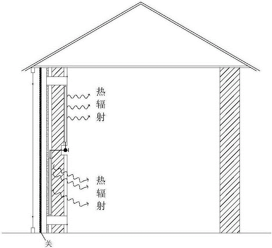
[0020] Referring to the accompanying drawings for details, this embodiment provides a passive solar wall, including a concrete wall 1 with inner and outer plastering layers, and a heat pipe evaporation section pipe grid 11 is arranged inside the outer surface plastering layer 3 of the concrete wall . The plastering layer 2 on the inner surface is provided with a grid 13 of the heat pipe condensing section. The grid of the heat pipe evaporating section is connected to the grid of the heat pipe condensing section through an intelligent control valve 12, and constitutes a heat pipe embedded wall. The outer side of the concrete wall is provided with a liftable louver grid 5 with reflective coating, and the outer side of the liftable louver grid with reflective coating is provided with a glass curtain wall 6 to form a solar heat exchange wall. The liftable louver grid with reflective coating is placed between the outer side of the concrete wall and the glass curtain wall at interval...


PUM


Abstract

The invention relates to a passive solar energy wall, which comprises a concrete wall body with internal and external plastering layers. The passive solar energy wall is characterized in that the external plastering layer of the concrete wall body is in internally provided with a heat pipe evaporation section transistor gate and the internal plastering layer of the concrete wall body is in internally provided with a heat pipe condensation section transistor gate. The heat pipe evaporation section transistor gate and the heat pipe condensation section transistor gate are connected via an intelligent control valve to form a heat pipe-imbedded wall. The outer side of the concrete wall body is provided with an elevating louver cascade with a reflective coating layer. The outer side of the reflective coating layer-contained louver cascade is provided with a glass curtain wall. The heat pipe-imbedded wall and the glass curtain wall together form the entirely passive solar energy wall and the wall can be southward, eastward or westward. According to the technical scheme of the invention, the internal and external surfaces of the wall are provided with heat pipe transistor gates, the glass curtain wall and a ventilation structure. Therefore, the phase change-based heat absorbing and releasing property and the air heat convection property during the natural gravity cycling process are realized based on a working medium inside a heat pipe. As a result, the heat exchange between the indoor environment and the outdoor environment is realized.

Description

technical field [0001] The invention belongs to building structures, in particular to a passive solar wall. Background technique [0002] In my country's total energy consumption, building energy consumption accounts for a considerable proportion and is increasing continuously. It was 20.7% in 2004, reached 30% in 2011, and is expected to reach about 35% in 2020. Building energy conservation is urgent. my country has now implemented 65% of building energy-saving standards, and plans to fully implement 75% of energy-saving standards in 2020. With the improvement of our country's requirements for building energy-saving standards, passive buildings with low energy consumption have become the trend of future development. Passive buildings refer to buildings that can use no or as little primary energy as possible to make the interior meet the comfort requirements, thereby reducing the building's dependence on active energy supply. The application of passive solar technology in...

Claims


Application Information

Patent Timeline
IPC IPC(8): E04B2/00E04B2/88F24F5/00
Inventor 张志刚孙晴
Owner TIANJIN CHENGJIAN UNIV
Learn More