
Ultra-wideband digital phase shifter

A digital phase shifter and ultra-wideband technology, applied in the field of phase shifters, can solve the problems that reflection circuits are difficult to meet the requirements of ultra-wideband frequency bands, increase circuit costs, and unfavorable integration, etc., and achieve compact structure, low insertion loss, and reduced circuit area effect

Active Publication Date: 2016-01-27
NANJING MILEWEI CORP
View PDF13 Cites 6 Cited by
  • Summary
  • Abstract
  • Description
  • Claims
  • Application Information

AI Technical Summary

Problems solved by technology

[0004] Reflective phase shifters are widely used in the design of broadband phase shifters. Traditional 3dB couplers such as Lange couplers have a large area, which is not conducive to integration and increases circuit costs; traditional reflective circuits are difficult to meet ultra-wideband The frequency band requirements

Method used


Image

  • Ultra-wideband digital phase shifter
  • Ultra-wideband digital phase shifter
  • Ultra-wideband digital phase shifter

Examples


specific Embodiment approach

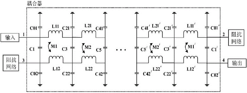
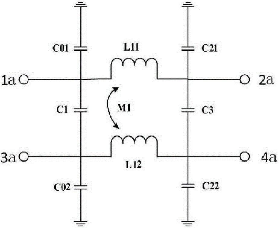
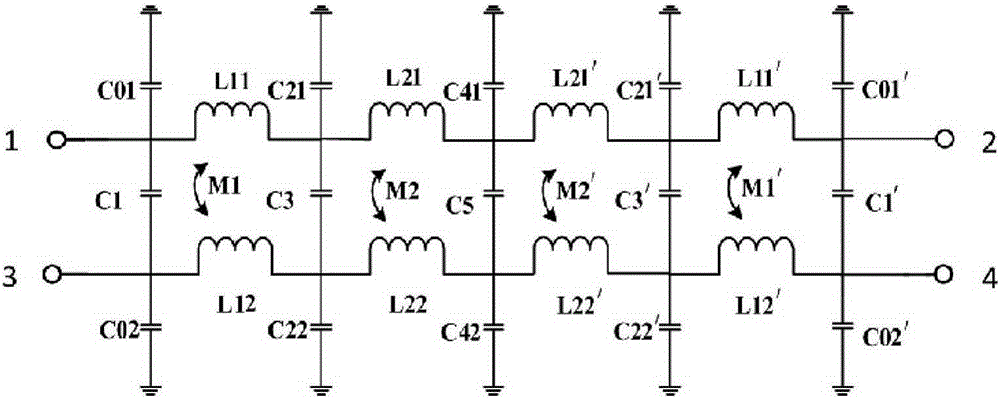
[0036] In order to widen the bandwidth, four spiral inductive coupling units are cascaded to form the attached image 3 In the UWB coupler shown in , ports 1, 2, 3, and 4 are the input end, straight-through end, coupling end, and isolation end of the UWB coupler, respectively, and they are the first, second, and The third and fourth stages of spiral inductive coupling units, each spiral inductive coupling unit is connected in series through the first spiral inductors of each level and the second spiral inductors of each level to achieve multi-level cascading, shared between the front and rear stages A jumper capacitor and a capacitor to ground located across the jumper capacitor. The structure of the coupler circuit is symmetrical up and down, left and right, that is, the structure of the first, second, third, and fourth spiral inductive coupling units is symmetrical with the horizontal center line and the vertical center line, image 3C01=C02=C01 flat center line and vertica...


PUM


Abstract

The invention discloses an ultra-wideband digital phase shifter. The phase shifter comprises a coupler and first and second impedance networks. The coupler is formed by spiral inductive coupling units through cascading. Each spiral inductive coupling unit comprises a first spiral inductor and a second spiral inductor which are mutually coupled. Multistage cascading of all the spiral inductive coupling units is realized by series connection all the first spiral inductors and series connection all the second spiral inductors. Coupling distance or microstrip line width of all the spiral inductive coupling units of the coupler gradually reduces from the external part to the internal part. The impedance networks are realized by adopting LC circuits and switch elements, and the state of the impedance networks is switched by the switches so that phase shifting is generated, and thus the structure is reasonable and realization is easy. The phase shifter is compact in structure, small in area occupation and great in wideband characteristics so that the phase shifter has great advantage and application space in an integrated chip application.

Description

technical field [0001] The invention relates to a phase shifter, in particular to a digital phase shifter. Background technique [0002] With the continuous development of broadband active phased array radar, people's demand for antenna beam control continues to increase, and the research on control circuits is also more in-depth. [0003] As a key component of beam control, the phase shifter has always been one of the key components in antenna transceiver components due to its many working states and technical indicators, large footprint, high performance requirements, and difficult design and manufacture. The development of phased array radar puts forward higher requirements on the bandwidth, phase shifting accuracy and integration area of ​​the phase shifter. Therefore, the research on broadband and ultra-wideband high-performance phase shifters has important significance and practical application value . [0004] Reflective phase shifters are widely used in the design ...

Claims


Application Information

Patent Timeline
Patent Type & Authority Applications(China)
IPC IPC(8): H01P1/18
CPCH03H7/09H03H7/185H03H7/19H01P1/18H01P1/184H01Q3/38
Inventor 杜璟蒋乐夏冬
Owner NANJING MILEWEI CORP
Learn More