
Anti-harmonic-wave reactive compensation capacitor module apparatus

A technology for compensating capacitors and harmonics, applied in the field of anti-harmonic reactive power dynamic compensation devices, can solve the problems of harmonic amplification, increased harmonic interference coefficient, lack of filtering function, accelerated equipment aging, etc., to achieve stable equipment The effect of operation, convenient installation, wiring, maintenance and repair, and saving installation space

Inactive Publication Date: 2016-01-27
重庆瑞升康博电气有限公司
View PDF0 Cites 2 Cited by
  • Summary
  • Abstract
  • Description
  • Claims
  • Application Information

AI Technical Summary

Problems solved by technology

Harmonics generated by these non-linear electrical equipment can lead to waste of electrical energy, reduce system capacity, accelerate equipment aging, reduce productivity, and can cause failure of the power distribution system itself or other equipment connected to the system
In the case of severe harmonics, ordinary capacitive reactive power compensation devices and dynamic capacitive reactive power compensation devices commonly used in low-voltage distribution networks do not have filtering functions, not only have no suppression of harmonics in civil low-voltage distribution networks, but also It will amplify the harmonics and increase the harmonic interference coefficient

Method used


Image

  • Anti-harmonic-wave reactive compensation capacitor module apparatus
  • Anti-harmonic-wave reactive compensation capacitor module apparatus
  • Anti-harmonic-wave reactive compensation capacitor module apparatus

Examples


Embodiment Construction

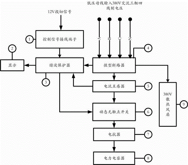
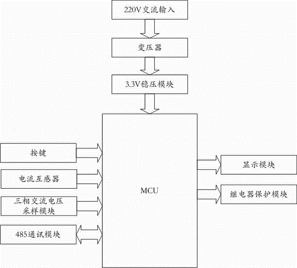
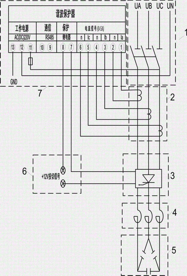
[0014] figure 1 It is the system block diagram of the anti-harmonic reactive power compensation capacitor module device. The anti-harmonic reactive power compensation capacitor module device includes miniature circuit breakers, current transformers, dynamic non-contact switches, reactors, power capacitors, harmonic protectors, display Screen, control signal terminals and 380V cooling fan. exist figure 1 The medium harmonic protector 3 plays an important role. It monitors the total current and harmonic current of the module through the current transformer 5; when the total current exceeds the set value, the three-phase current imbalance and the total harmonic exceed the limit, it passes the harmonic The internal relay of the protector 3 disconnects the 12V input signal coming in from the control signal terminal, and at the same time the output control signal disconnects the dynamic non-contact switch 6 to disconnect the power capacitor 8, so as to prevent overcurrent, current ...


PUM


Abstract

The invention relates to a reactive power compensator, especially to an anti-harmonic-wave reactive compensation capacitor module apparatus. The anti-harmonic-wave reactive compensation capacitor module apparatus comprises a breaker module, a current transformer module. A dynamic noncontact switch module, a reactor module, a harmonic wave protector module, a switch signal input terminal module, a compensation capacitor module and a heat dissipation fan, which are all connected together. Power factors of a system is increased, energy consumption is reduced, the voltage quality of a power grid is improved, equipment is stabilized to function, the electric quality is improved while the power supplying efficiency of a power grid is increased, and harmonic waves generated by a load can be effectively filtered. Therefore, harmonic waves of a low voltage distribution network for civil uses are inhibited within a national standard, harmonic wave currents are prevented from damaging power supplying equipment, and the electric quality of a low voltage distribution network for civil uses and the safety of the network are improved. Furthermore, the installing space of equipment is effectively saved, the equipment is made to have a concise internal structure and is convenient to maintain, the reactive compensation apparatus is improved in reliability and safety, and maintenance technical difficulties are minimized.

Description

technical field [0001] The invention relates to a reactive power compensation device, in particular to an anti-harmonic reactive power dynamic compensation device. Background technique [0002] At present, the application of power electronic equipment is becoming more and more common. Power electronic devices are indispensable in the production process, such as personal computers, air-conditioning equipment, lighting equipment, elevators, DC motors, frequency converters, intermediate frequency induction furnaces, medical equipment, etc. The harmonics generated by these non-linear electrical equipment can lead to waste of electric energy, reduce system capacity, accelerate equipment aging, reduce productivity, and can cause failure of the power distribution system itself or other equipment connected to the system. In the case of severe harmonics, ordinary capacitive reactive power compensation devices and dynamic capacitive reactive power compensation devices commonly used in...

Claims


Application Information

Patent Timeline
IPC IPC(8): H02J3/01H02J3/18
CPCY02E40/30Y02E40/40
Inventor 陈军冯伟杨波杜春荣胡涛
Owner 重庆瑞升康博电气有限公司
Learn More