Exhaust gas purification system used on injection molding machine

An exhaust gas purification system and injection molding machine technology, applied in the field of parts or accessories, can solve problems such as tuberculosis, human injury, and environmental pollution, and achieve the effect of high water recycling value and good effect

Inactive Publication Date: 2016-02-03
CHONGQING JIAYU SHIJI PLASTIC IND
View PDF10 Cites 9 Cited by
  • Summary
  • Abstract
  • Description
  • Claims
  • Application Information

AI Technical Summary

Problems solved by technology

[0002] A large amount of harmful gas (smoke) containing dust particles will be produced in the process of plastic processing. Since these harmful gases are polluting, direct discharge into the air will not only cause physical harm to the staff, but also pollute the environment. In the injection molding machine In the field of production of daily plastic products, due to the low economic added value of the product, the on-site operation of the injection molding machine requires a lot of manpower. When the injection molding is taken out, a large amount of yellow smoke of dust particles will be generated near the mold. These Most of the smoke will be scattered in the air. The operator needs to be close to the mold at a distance of 20-30cm when taking the material. The operator will inadvertently breathe the smoke. The smoke contains dioxins, which is very harmful to the human body. , it destroys the immune system in the human body and is the number one accomplice of leukemia. In addition, dust particles can easily cause lung diseases of operators. Operators who work in such an environment for a long time will experience hair loss, dizziness, and easy to get sick. tuberculosis

Method used


Image

  • Exhaust gas purification system used on injection molding machine
  • Exhaust gas purification system used on injection molding machine

Examples


Embodiment Construction

[0015] The invention will be further described in detail below in conjunction with the accompanying drawings and specific embodiments.

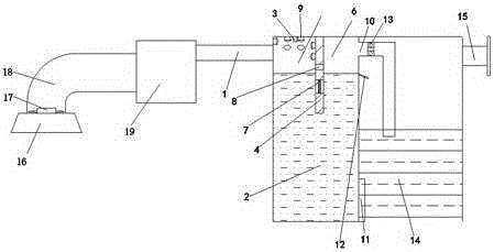
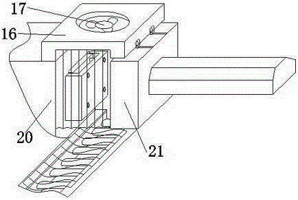
[0016] Such as figure 1 Shown is the structural representation of the exhaust gas purification system used on the injection molding machine of the present invention; figure 2 Shown is a schematic structural view of the collection channel used in the waste gas purification system on the injection molding machine of the present invention; a waste gas purification system used on the injection molding machine of the present invention includes a movable bracket 21 and a fixed bracket 20 on the injection molding machine, the The top of the movable support 21 and the fixed support 20 is provided with a waste gas collection cover 16, the top of the collection cover 16 is provided with a fan 17 and a ventilation pipe 18 covered on the fan 17, and the ventilation pipe 18 communicates with a collection channel 19, an air intake pipe 1 , an exhaust gas...


PUM


Abstract

The invention provides an exhaust gas purification system used on an injection molding machine. The exhaust gas purification system comprises a movable bracket and a fixed bracket, wherein a collection cover, an air blower and a ventilation pipe are arranged at the tops of the movable bracket and the fixed bracket; the ventilation pipe is communicated with a collection channel, a gas inlet pipe, an exhaust gas treatment box and a filtering tank; a partition wall for diving the exhaust gas treatment box is arranged in the exhaust gas treatment box; sprinkler heads are arranged in a sprinkling chamber; a gas vent and a filtering net are arranged on the partition wall; an exhaust pipe is arranged at the top of an exhaust chamber; an overflow weir is arranged between the exhaust chamber and a filtering tank; the filtering tank is arranged to be a closed filtering tank; an exhaust pipe I and an activated carbon adsorbent are arranged at the top of the filtering tank. According to the invention, exhaust gas is subjected to prefiltration through the sprinkling chamber and then introduced to a position below the liquid level of the filtering tank through the gas vent to be subjected to secondary filtration, and sewage in the sprinkling chamber enters the exhaust chamber through the underwater filtering net, and then is subjected to secondary filtration through the overflow weir, so that exhaust gas is sprinkled sufficiently, and smoke particles flocculate and precipitate on a water area above the filtering net, therefore, the exhaust gas treatment effect is good and the water recycling value is high.

Description

technical field [0001] The invention belongs to the technical field of parts, components or accessories; auxiliary operation, and in particular relates to an exhaust gas purification system used on an injection molding machine. Background technique [0002] In the process of plastic processing, a large amount of harmful gas (smoke) containing dust particles will be produced. Since these harmful gases are polluting, direct discharge into the air will not only cause physical harm to the staff, but also pollute the environment. In the injection molding machine In the field of production of daily plastic products, due to the low economic added value of the product, the on-site operation of the injection molding machine requires a lot of manpower. When the injection molding is taken out, a large amount of yellow smoke of dust particles will be generated near the mold. These Most of the smoke will be scattered in the air. The operator needs to be close to the mold at a distance of...

Claims


Application Information

Patent Timeline
Patent Type & Authority Applications(China)
IPC IPC(8): B01D53/04B01D47/12C02F1/52B29C45/17B08B15/02
Inventor 郑侑宗陈吴军王国成
Owner CHONGQING JIAYU SHIJI PLASTIC IND
Why Eureka
Try Eureka