Adsorbent compressing device used in pressure-swing absorber and adsorbent compressing method thereof
A pressure swing adsorption and compression device technology, applied in separation methods, chemical instruments and methods, gas fuels, etc., can solve the problems of inability to adjust the height of the upper orifice plate, uneven distribution of adsorption towers, cumbersome compression process, etc. The effect of reducing leakage and escape, good practicability and simple pressing operation process
- Summary
- Abstract
- Description
- Claims
- Application Information
AI Technical Summary
Problems solved by technology
Method used
Image
Examples
specific Embodiment approach 1
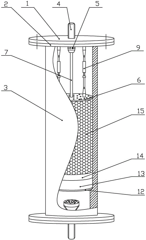
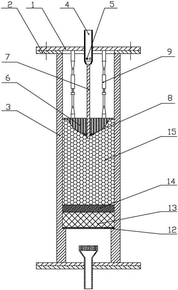
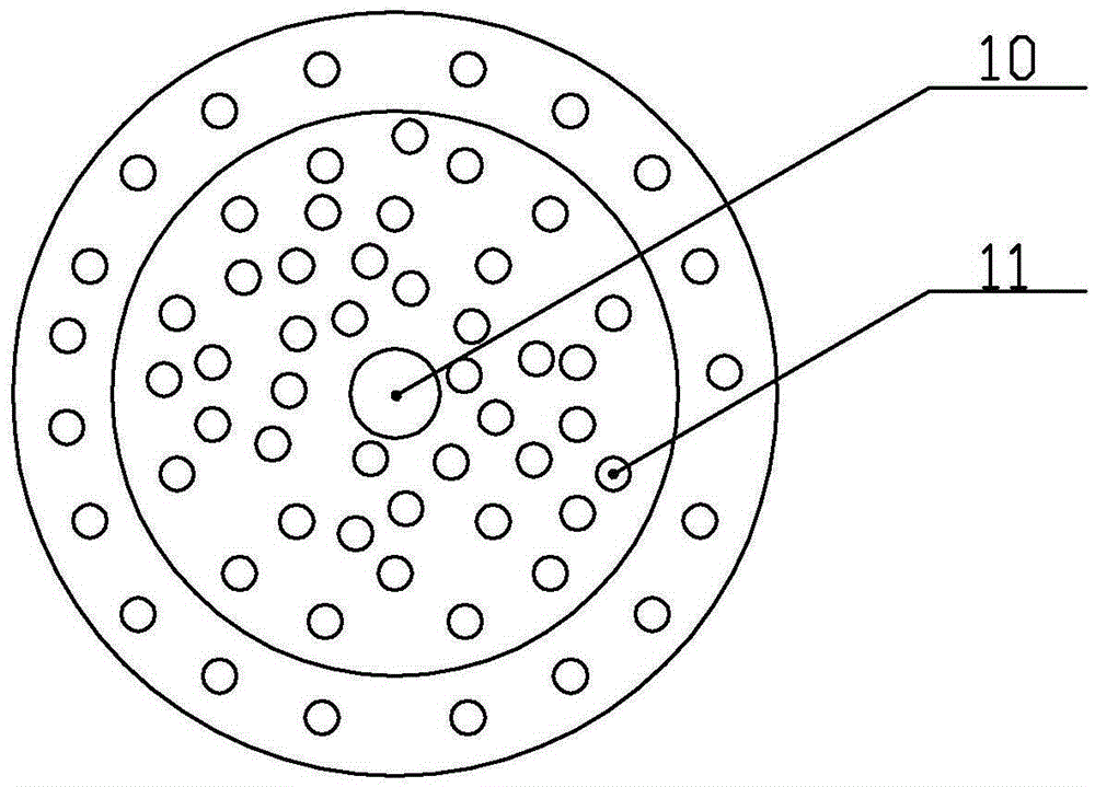
[0016] Specific implementation mode one: combine Figure 1 ~ Figure 3 This embodiment is described. This embodiment is used for the compression device of the adsorbent in the pressure swing adsorption tower, including the cover plate 1, the flange plate 2 and the tower body 3, the tower body 3 is cylindrical, and the lower end of the flange plate 2 It is fixedly connected with the upper end of the tower body 3, and the center of the cover plate 1 is equipped with an air outlet pipe 4, and the air outlet pipe 4 is fixedly connected with the cover plate 1, and the lower part of the air outlet pipe 4 is processed with several air outlet holes 5 along its circumferential direction, and the cover plate 1 Located on the upper end of the flange 2 and fixed to the flange 2 by bolts, the compression device used for the adsorbent in the pressure swing adsorption tower also includes an upper orifice plate 6, a guide rod 7, a head 8 and a number of elastic fixing rods 9. The upper orifice...
specific Embodiment approach 2
[0020] Specific implementation mode two: combination figure 1 and figure 2 To describe this embodiment, the number of the elastic fixing rods 9 is three. Such a design can make the structure of the device simple while ensuring the compressed state of the adsorbent. Other compositions and connections are the same as those in the first embodiment.
specific Embodiment approach 3
[0021] Specific implementation mode three: combination figure 2 To describe this embodiment, the inner diameter of the flange 2 is consistent with the inner diameter of the tower body 3 . Designed in this way, it is convenient to install the lower orifice plate 12. Other compositions and connections are the same as those in the first embodiment.
[0022] Specific implementation mode four: combination figure 1 and figure 2 To illustrate this embodiment, the elastic fixing rod 9 is a lockable pneumatic spring. Such design facilitates the adjustment of the height of the upper orifice plate 6 and ensures the compression of the adsorbent. Other compositions and connections are the same as those in Embodiment 1, 2 or 3.
[0023] Specific implementation mode five: combination figure 1 and figure 2 To illustrate this embodiment, the elastic fixing rod 9 is a friction type pneumatic spring. Such design facilitates the adjustment of the height of the upper orifice plate 6 and...
PUM
| Property | Measurement | Unit |
|---|---|---|
| Length | aaaaa | aaaaa |
Abstract
Description
Claims
Application Information
 - R&D
- Intellectual Property
- Life Sciences
- Materials
- Tech Scout
- Unparalleled Data Quality
- Higher Quality Content
- 60% Fewer Hallucinations
Browse by: Latest US Patents, China's latest patents, Technical Efficacy Thesaurus, Application Domain, Technology Topic, Popular Technical Reports.
© 2025 PatSnap. All rights reserved.Legal|Privacy policy|Modern Slavery Act Transparency Statement|Sitemap|About US| Contact US: help@patsnap.com


