Aircraft skin no-allowance milling flexible tool and application method thereof

A technology for aircraft skinning and cutting flexibility, applied to workpieces, positioning devices, milling machine equipment, etc., can solve the problems of insufficient freedom degree constraints, large dimensions of support rods, insufficient clamping rigidity, etc., to save the cost of the servo system and improve the Milling accuracy, the effect of simplified functions and structures

Active Publication Date: 2016-02-03
SHENYANG AIRCRAFT CORP
View PDF6 Cites 15 Cited by
  • Summary
  • Abstract
  • Description
  • Claims
  • Application Information

AI Technical Summary

Problems solved by technology

Press as Figure 17 The typical milling and cutting flexible tooling shown in the calculation requires 80 sets of servo transmission systems, each system needs at least 15,000 yuan, and the entire system needs 1.2 million yuan, resulting in very high development costs for existing flexible tooling
[0005] 2. It is difficult to expand the application of flexible tooling
The difficulty and workload of these tasks is no less than that of reinstalling and debugging a set of equipment, so it is actually not feasible to expand the number of suction cups
[0006] 3. The clamping rigidity of the flexible tooling to the thin-walled skin is insufficient
The servo transmission system used in the existing flexible tooling support rods needs a large volume, and it must also ensure the clamping rigidity, resulting in a large size of each support rod, which in turn results in a large spacing between the dot matrix (about 300mm ~ 400mm)
Such a large discrete spacing is difficult to ensure the support stiffness of the thin skin after clamping
2) Insufficient clamping rigidity caused by the suction cup can swing with the movement. The suction cup of the existing flexible tooling can swing with the movement, which will cause insufficient constraints on the three rotational degrees of freedom around the center of the sphere when the suction cup clamps the thin skin, affecting Clamping stiffness
3) The clamping rigidity caused by the non-edge clamping device is insufficient. When the existing flexible tooling clamps the skin, it does not clamp the skin outside the edge line, causing the skin outside the edge line to be in a cantilever state, so it is subjected to cutting force greater vibration
[0007] 4. The actual clamping state of the skin is inconsistent with the assembly digital model state used to compile the NC program
The flexible tooling assembly hole locator relies on workers to manually complete the positioning and locking of the x-axis, y-axis, z-axis, A angle, and C angle. The positioning accuracy of each axis is relatively large, resulting in the relative position of the actual clamped skin and the origin of the tool It is inconsistent with the relative position in the assembly digital model, and the NC machining program is compiled based on the three-dimensional assembly digital model, which will cause the overall deviation of the processed skin compared with the digital model
2) The shape and surface of the skin in the actual clamping and assembly of the digital model are inconsistent. On the one hand, due to the large distance between the suction cups, the surface fitted with the suction cup clamping points as discrete points is difficult to be consistent with the theoretical shape and surface, and the edge difference is even greater ; On the other hand, the suction cup of the flexible tooling can swing with the movement, and the clamping (adsorption) of the suction cup is elastic, which will cause the actual suction cup clamping point to be inconsistent with the discrete points of the shape and surface, and the shape and surface after adsorption are inconsistent with the theoretical inconsistent shape
Due to the deficiencies in the above four aspects, the flexible tooling cannot be widely used in actual production

Method used


Image

  • Aircraft skin no-allowance milling flexible tool and application method thereof
  • Aircraft skin no-allowance milling flexible tool and application method thereof
  • Aircraft skin no-allowance milling flexible tool and application method thereof

Examples


Embodiment Construction

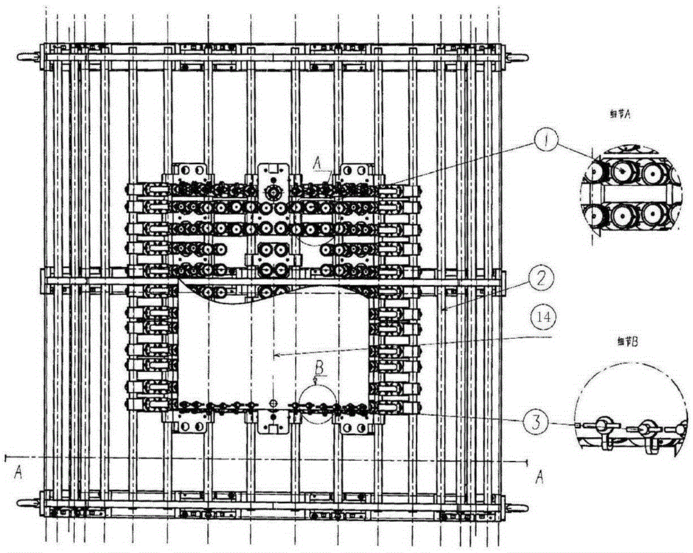
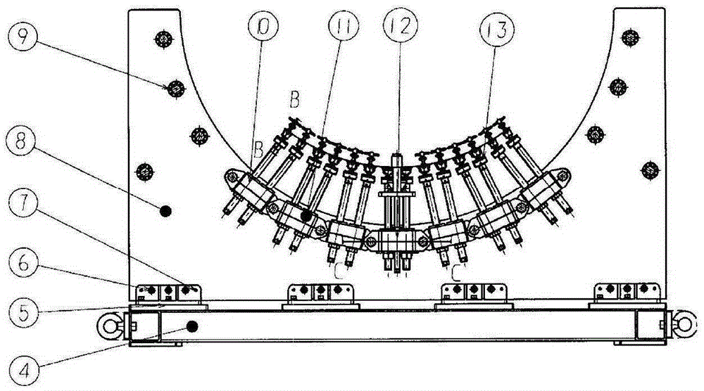
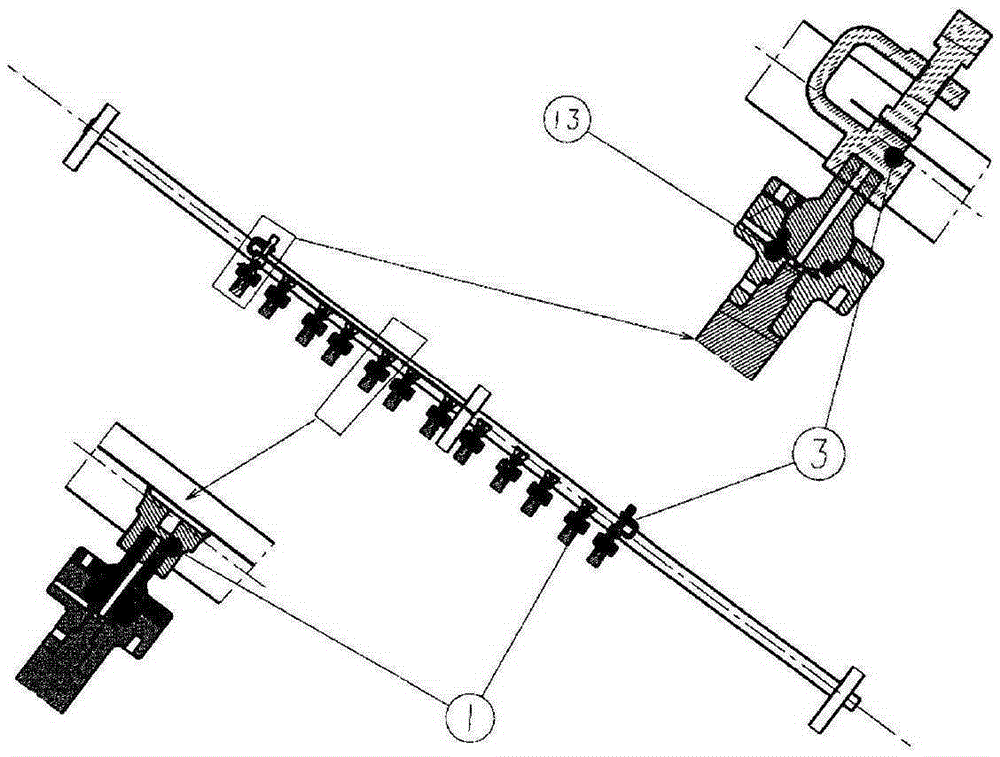
[0045] Such as Figure 1-16 A flexible tooling for milling and cutting aircraft skin without allowance is shown, such as figure 1 The shown flexible tooling includes a tooling frame, several double-bar support units 10, several four-bar support units 11 and several reference support units 12 arranged on the tooling frame; Figure 2-4 The tooling frame shown has a base 4, on which a connecting bracket 5 is provided, and on the connecting bracket 5, several assembling-type supporting plates 8 are provided, and the following supporting plates 8 and the connecting bracket 5 pass through the fastening assembly 6 and the positioning pin 7 are fastened on the base 4; each conformal support plate 8 is provided with several mounting holes, and the mounting holes are equipped with tensioning sleeves 9, and the connecting rods 2 are sequentially penetrated into the coaxial joints on the conformal support plate 8. In the installation hole, the connecting rod 2 and the follow-up support ...


PUM


Abstract

The invention discloses an aircraft skin no-allowance milling flexible tool. Multiple double-rod support units, multiple four-rod support units and multiple reference support units are arranged on a tool frame; bulb locking mechanisms are mounted on the double-rod support units and the four-rod support units; suckers or edge clampers are mounted on the bulb locking mechanisms; machining zero adaptors and assembly hole adaptors are arranged on the reference support units; the tool frame has a base; a connecting bracket is arranged on the base; a random support plate is arranged on the connecting bracket; multiple mounting holes are formed in the random support plate; expansion sleeves are mounted in the mounting holes; connecting rods are inserted in the coaxial mounting holes, and are locked through the expansion sleeves, so that the connecting rods and the random support plate are fastened; and the double-rod support units, the four-rod support units or the reference support units are mounted on the connecting rods. The aircraft skin no-allowance milling flexible tool has the advantages of simple structure, low cost, extensibility of modular structure, high clamping rigidity of thin-wall skin and convenience for application and promotion.

Description

technical field [0001] The invention relates to the technical field of aircraft skin milling without margin, in particular to a flexible tooling for milling without margin of aircraft skin and its use method. Background technique [0002] The traditional aircraft skin margin removal method is to fix the skin blank on a special trimming die, and the workers manually operate the cutting equipment to trim the edge according to the model, which requires a large amount of labor and low trimming accuracy. Therefore, the milling and cutting of skin blanks by adopting the skin non-residue CNC milling process based on suction cup-type flexible tooling (flexible tooling) can significantly improve the quality and efficiency of milling and reduce the number of tooling, and is the main method to achieve no-residue milling of skin . [0003] However, most of the sucker-type flexible tooling used in the existing skin-free CNC milling process is the most typical flexible tooling structure-...

Claims


Application Information

Patent Timeline
Patent Type & Authority Applications(China)
IPC IPC(8): B23Q3/06B23Q3/08B23C3/00
CPCB23C3/00B23C2215/04B23Q3/062B23Q3/088
Inventor 白新宇迟彩楼白继鹏
Owner SHENYANG AIRCRAFT CORP
Why Eureka
Try Eureka