Surging molten iron slag-off method

A technology for slag removal and molten iron, which is applied in the field of slag removal technology in molten iron tanks, can solve the problems of increasing the gas supply strength, shortening the life of the jet gun, and accelerating the erosion of molten iron, etc. , Conducive to the effect of slag aggregation

Active Publication Date: 2016-02-03
ANGANG STEEL CO LTD
View PDF7 Cites 3 Cited by
  • Summary
  • Abstract
  • Description
  • Claims
  • Application Information

AI Technical Summary

Problems solved by technology

The jet gun of this method is also inserted into the molten iron obliquely, which inevitably produces a certain deflection, resulting in micro-cracks in the refractory material on the upper surface of the jet gun under the action of tension, which accelerates the erosion of molten iron and shortens the life of the jet gun
Moreover, the spray gun cannot move left and right in the horizontal direction during the slag removal process, so that at the end of slag removal, that is, when the amount of residue is less than 1 / 5 of the total amount of slag, it is difficult to gather the residue to the Together, and the gas supply intensity exceeds a certain value, it will cause the risk of molten iron splashing

Method used


Image

  • Surging molten iron slag-off method

Examples


Embodiment 1

[0021] The amount of slag on the top of the molten iron is 3kg / t, the ratio of the clearance of the molten iron tank 8 to the diameter of the tank mouth is 0.13, and the temperature of the molten iron is 1400°C.

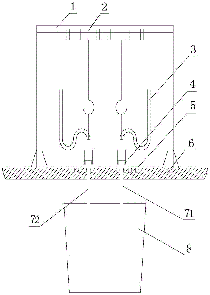
[0022] Iron ladle 8 is inclined 23 °. Start the hoist crane 2 and start to lower the A spray gun 71 and the B spray gun 72, so that the positioning pin 4 accurately falls into the positioning hole 5 on the operating platform 6, and the air supply valve of the air supply hose 3 is opened at the same time as the gun is lowered to control the intensity of the air supply 3NL / (min·t), pressure 0.75MPa.

[0023] Insert the A jet gun 71 and the B jet gun 72 vertically into the molten iron simultaneously from the top of the molten iron tank 8, the distance between the A jet gun 71 and the B jet gun 72 is 1 / 2 of the radius length of the tank mouth, and the insertion depth is 1 / 2 of the depth of the molten iron. The gas supply intensity of A jet gun 71 is constant, and the ga...

Embodiment 2

[0026] The amount of slag on the top of the molten iron is 5kg / t, the ratio of the clearance of the molten iron tank 8 to the diameter of the tank mouth is 0.16, and the temperature of the molten iron is 1350°C.

[0027] Iron ladle 8 is inclined 24 °. Start the hoist crane 2 and start to lower the A spray gun 71 and the B spray gun 72, so that the positioning pin 4 accurately falls into the positioning hole 5 on the operating platform 6, and the air supply valve of the air supply hose 3 is opened at the same time as the gun is lowered to control the intensity of the air supply 2NL / (min·t), pressure 0.70MPa.

[0028] Insert the A jet gun 71 and the B jet gun 72 vertically into the molten iron simultaneously from the top of the molten iron tank 8, the distance between the A jet gun 71 and the B jet gun 72 is 1 / 2 of the radius length of the tank mouth, and the insertion depth is 2 / 3 of the depth of the molten iron. The gas supply intensity of A jet gun 71 is constant, and the ga...

Embodiment 3

[0031] The amount of slag on the top of the molten iron is 10kg / t, the ratio of the clearance of the molten iron tank 8 to the diameter of the tank mouth is 0.2, and the temperature of the molten iron is 1300°C.

[0032] Iron ladle 8 is inclined 25 °. Start the hoist crane 2 and start to lower the A spray gun 71 and the B spray gun 72, so that the positioning pin 4 accurately falls into the positioning hole 5 on the operating platform 6, and the air supply valve of the air supply hose 3 is opened at the same time as the gun is lowered to control the intensity of the air supply 2NL / (min·t), pressure 0.70MPa.

[0033] Insert the A jet gun 71 and the B jet gun 72 vertically into the molten iron simultaneously from the top of the molten iron tank 8, the distance between the A jet gun 71 and the B jet gun 72 is 1 / 2 of the radius length of the tank mouth, and the insertion depth is 3 / 4 of the depth of the molten iron. The gas supply intensity of A jet gun 71 is constant, and the ga...


PUM


Abstract

The invention provides a surging molten iron slag-off method. Two air injection guns are perpendicularly inserted into molten iron from the top of a molten iron tank. The interval between the two guns is 1/2 of the radius of a tank opening, the insertion positions are located at the points 1/2 of the radius of the tank opening, and the insertion depth ranges from 0.5 m to 2.5 m; the air supply intensity is controlled to be larger than or equal to 2 NL/(min t) and the pressure is larger than 0.7 MPa; the air supply intensity of the air injection gun A is controlled to be 2 NL/(min t), the air supply intensity of the air injection gun B is gradually increased till the molten iron boiling exposed face makes contact with the wall of the molten iron tank, the air supply intensity of the air injection gun A is adjusted to be the same as that of the air injection gun B till the area of the molten iron boiling exposed face is larger than 1/2 of the tank opening of the molten iron tank, and therefore slag-off operation is started; after slag-off operation is finished, the air injection guns are pulled out of the molten iron and inject air continuously for over 30 s; and hoist cranes are used for lifting the air injection guns, so that locating pins are away from locating holes from 190 mm to 210 mm, the hoist cranes are transversely moved till the interval between the two guns reaches the length of the radius of the tank opening and then the hoist cranes fall, and the locating pins fall into new locating holes. By the adoption of the surging molten iron slag-off method, slag-off time can be shortened and iron loss and the converter resulfurization amount generated in the desulfuration slag-off process can be effectively reduced.

Description

technical field [0001] The invention belongs to the technical field of slag removal from molten iron tanks, and particularly relates to a kind of method that does not use a slag accumulating agent after desulfurization, desiliconization and dephosphorization of molten iron, but utilizes the phenomenon of springing formed by blowing gas from an air jet gun to push the top slag of the molten iron tank to The slag removal port is easy to remove the slag and reduce the loss of molten iron. Background technique [0002] After desulfurization, dephosphorization, and desiliconization of molten iron, in order to prevent problems such as "returning sulfur" and "returning phosphorus" in subsequent processes, and increasing metallurgical lime consumption, it is necessary to remove the top slag after the third desulfurization of molten iron. In order to remove the top slag smoothly, the current conventional method is to put in a slag accumulator to make the top slag with good fluidity v...

Claims


Application Information

Patent Timeline
Patent Type & Authority Applications(China)
IPC IPC(8): C21C7/072B22D43/00
CPCY02P10/20
Inventor 万雪峰曹东张晓光李广帮郭庆涛朱晓雷王丽娟于丽华
Owner ANGANG STEEL CO LTD
Why Eureka
Try Eureka