Turbine wheel of an exhaust gas turbocharger and associated production method

A technology of exhaust turbine and supercharger, which is applied in the field of turbine to achieve the effect of improving the center of gravity and low quality

Inactive Publication Date: 2016-02-03
BOSCH MAHLE TURBO SYST GMBH & CO KG
View PDF4 Cites 2 Cited by
  • Summary
  • Abstract
  • Description
  • Claims
  • Application Information

AI Technical Summary

Problems solved by technology

When casting Ni-base alloys and TiAl, the turbine is now initially cast from the front, i.e. from the turbine nose, where the casting process is somewhat

Method used


Image

  • Turbine wheel of an exhaust gas turbocharger and associated production method
  • Turbine wheel of an exhaust gas turbocharger and associated production method
  • Turbine wheel of an exhaust gas turbocharger and associated production method

Examples


Embodiment Construction

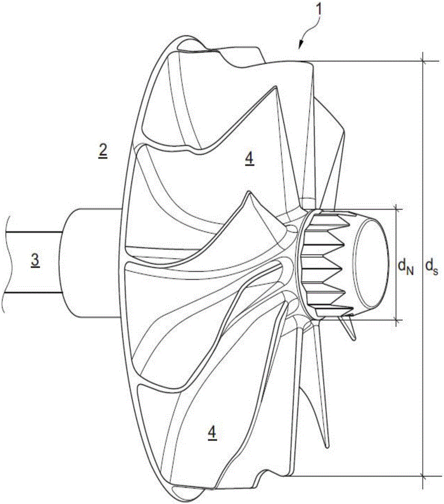
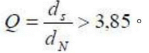
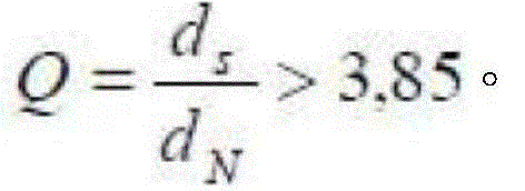
[0023] exist figure 1 In the case where the turbine 1 according to the invention can be designed as a turbine in the exhaust-gas turbocharger 2, the quotient: Q = d s d N > 3,85 .

[0024] Furthermore, the turbine 1 according to the invention is produced from titanium-aluminum alloy by means of metal injection molding (MIM), selective laser melting (SLM) or electron beam melting (EBM). In this case, the turbine 1 is connected to the shaft 3 (for example welded to the shaft 3 ) and forms in process the rotor of the exhaust-gas turbocharger 2 .

[0025] By producing the turbine 1 according to the invention by means of the mentioned production method and by means of titanium-aluminum alloys, a significantly reduced weight can be achieved compared to conventional turbines based on nickel-based alloys, while this low weight also r...


PUM


Abstract

The invention relates to a turbine wheel of an exhaust gas turbocharger which may include a body composed of a TiAl alloy via at a metal injection moulding (MIM), selective laser melting (SIM) or electron beam melting (EBM). The body may have a quotient Q of a diameter dS defined by each of the outlet blade tips to a diameter dN defined by each of the outlet blade roots corresponding to the following relationship: Q=dS/dN>3.85 in this condition.

Description

technical field [0001] The invention relates to a turbine of an exhaust-gas turbocharger. Furthermore, the invention relates to an exhaust-gas turbocharger having such a turbine and a method for producing such a turbine. Background technique [0002] In addition to the already proven turbines made of nickel-based alloys, weight-optimized turbines have been gradually considered in recent years, which utilize, inter alia, light metal alloys and ceramic materials. The advantage of a weight-optimized turbine in this case is that the mass moment of inertia is reduced, and the transient behavior of the exhaust-gas turbocharger is improved because it is equipped with such a weight-optimized turbine. For this purpose, titanium-aluminum alloys (γ-TiAl) are used, since titanium-aluminum alloys are approximately 50% less dense than commonly used nickel-based alloys. [0003] Today, these Ti-Al turbines are mainly produced by casting process. When casting Ni-based alloys and TiAl, th...

Claims


Application Information

Patent Timeline
IPC IPC(8): F01D5/28B23P15/02F02C6/12F01D5/04
CPCF05D2230/211F01D5/048F05D2220/40F05D2230/22F05D2300/174F02C6/12B23K2101/001B23K2103/14F02B37/00Y02T10/12Y02P10/25B22F10/28B33Y10/00B33Y80/00B23K26/342B22F3/225B22F5/009B23K15/0086B23K15/0093B23K26/0006F01D5/02F05D2230/23F05D2230/60F05D2240/24
Inventor 托马斯·施特里德尔迈尔约亨·施拉耶安东·安格卢什安德烈亚斯·施特伦佩尔京特·温克勒谢诺尔·瑟于特
Owner BOSCH MAHLE TURBO SYST GMBH & CO KG
Why Eureka
Try Eureka