
Automatic buckling machine for wave-soldering jig

A wave soldering fixture and automatic technology, which is applied to the assembly of printed circuits with electrical components, electrical components, and printed circuit manufacturing. The effect of improving efficiency

Active Publication Date: 2016-02-03
SHENZHEN MIGHT TECH
View PDF5 Cites 3 Cited by
  • Summary
  • Abstract
  • Description
  • Claims
  • Application Information

AI Technical Summary

Problems solved by technology

[0004] Most of the current positioning and clamping of circuit boards and pallets is manual operation, and there is no effective solution, but manual operation has the following disadvantages:
[0005] 1) Affect the quality: Since most of the circuit boards are small in thickness, manual handling should be done carefully, and it cannot be placed in place at one time when it is placed in the positioning slot, which will cause friction between the circuit board and the tray and affect the quality
[0006] 2) Affecting process parameters: Since manual placement cannot maintain consistency, this will have a certain impact on the processing of subsequent processes
[0007] 3) Affecting efficiency: manual operation should be handled with care when taking out the circuit boards, and one by one locks should be used when locking the circuit boards, which will take a long time and seriously affect work efficiency

Method used

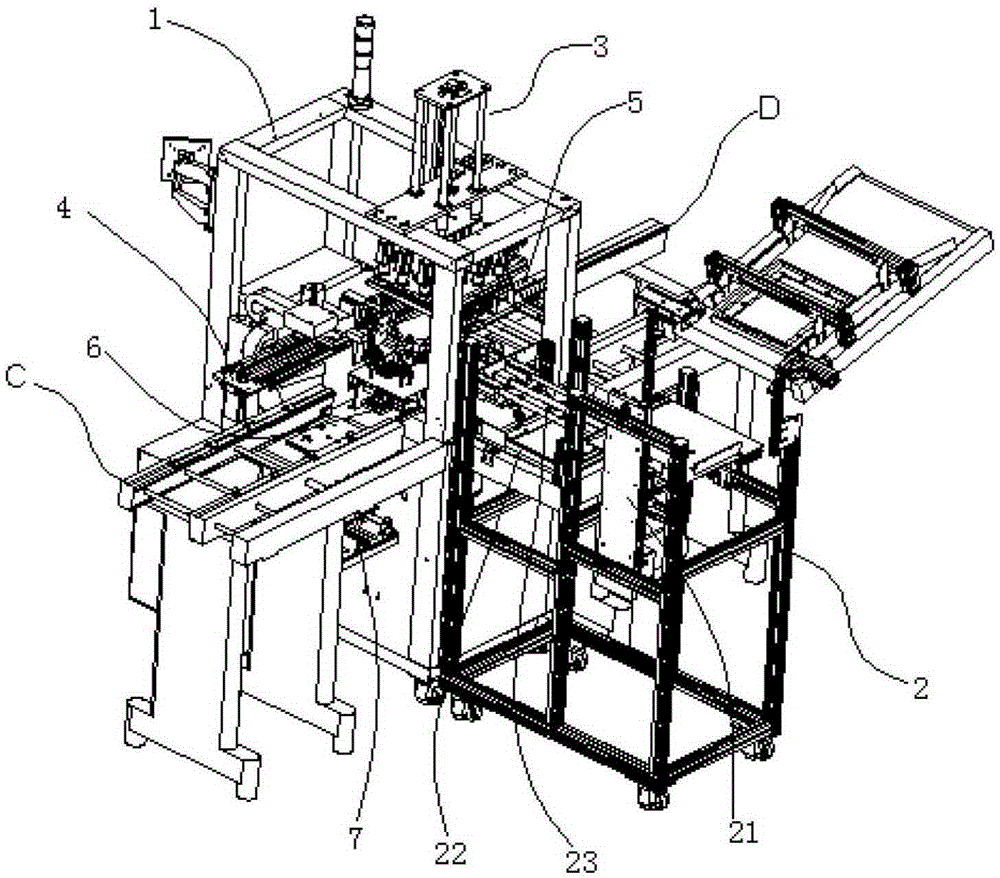

Image

  • Automatic buckling machine for wave-soldering jig
  • Automatic buckling machine for wave-soldering jig
  • Automatic buckling machine for wave-soldering jig

Examples


Embodiment Construction

[0033] In order to make the object, technical solution and advantages of the present invention clearer, the present invention will be further described in detail below in conjunction with the accompanying drawings and embodiments. It should be understood that the specific embodiments described here are only used to explain the present invention, not to limit the present invention.

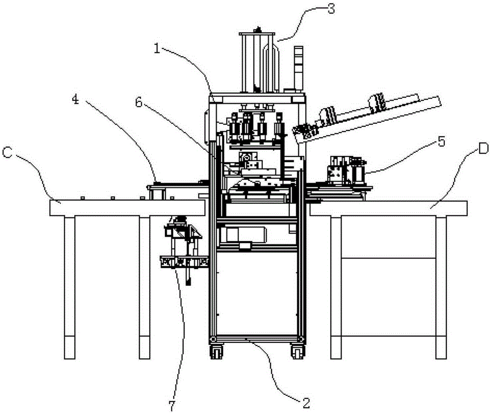
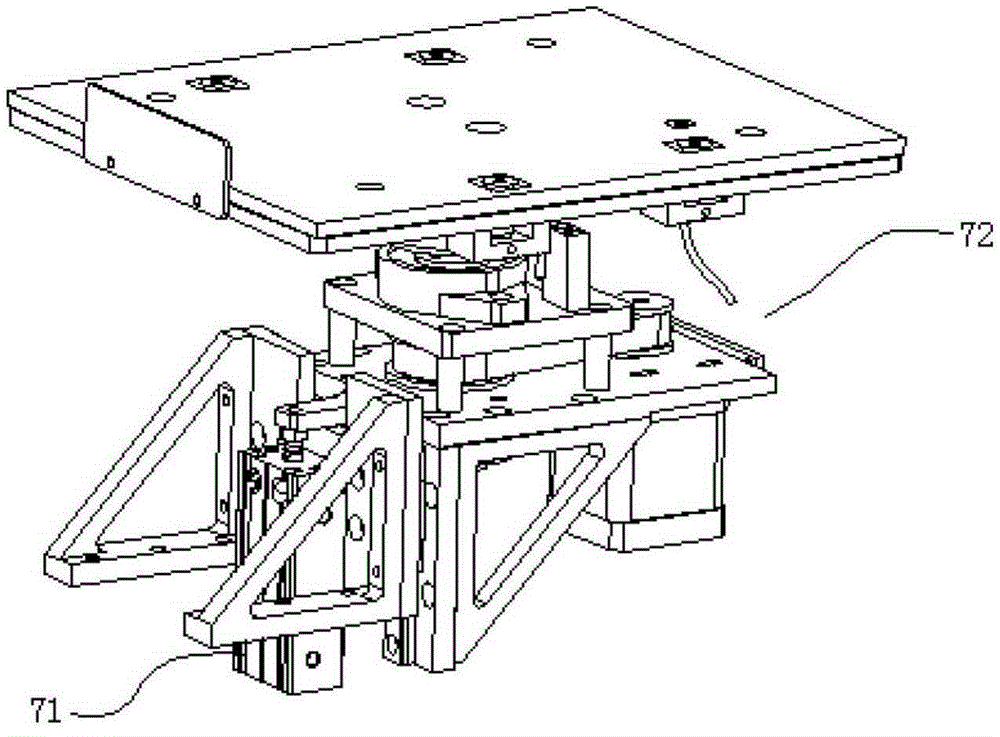
[0034] refer to figure 1 , 2 As shown, the present invention discloses an automatic buckle-up machine for wave soldering jigs, which includes: buckle-up welding frame 1, plate receiving mechanism 2, buckle-up Z-axis 3, main board pick-and-place mechanism 4, jig Pick-and-place mechanism 5, jig positioning mechanism 6 and jacking and rotating mechanism 7; wherein:

[0035] The buckle Z-axis 3 is fixed on the top of the buckle welding frame 1; the main board pick-and-place mechanism 4 is fixed on the left side of the platform of the buckle-up welding frame 1; the jig pick-and-place mechanism 5 is co...


PUM


Abstract

The invention discloses an automatic buckling machine for a wave-soldering jig, and the buckling machine comprises a buckling welding rack, a disc receiving mechanism, a buckling Z shaft, a mainboard taking and placing mechanism, a jig taking and placing mechanism, a jig positioning mechanism, and a jacking rotating mechanism. The buckling Z shaft is fixedly disposed above the buckling welding rack. The mainboard taking and placing mechanism is fixedly disposed at the left side of a platform of the buckling welding rack. The jig taking and placing mechanism is correspondingly disposed at the right side of the platform of the buckling welding rack in a fixed manner. The jig positioning mechanism is fixedly arranged exactly below the jig taking and placing mechanism and the mainboard taking and placing mechanism in a centralized manner. The disc receiving mechanism is in butt joint with the front surface of the jig positioning mechanism. The left and right sides of the buckling welding rack are respectively in butt joint with a factory production line. The jacking rotating mechanism is located at the left side of the buckling welding rack. The buckling Z shaft is provided with a buckling valve assembly. The disc receiving mechanism is provided with a disc receiving lifting shaft, a jig production line, and a disc pushing assembly. According to the invention, the machine takes a circuit board through vacuum absorption, and cannot cause friction and collision to damage the circuit board during taking and placing.

Description

technical field [0001] The invention relates to the technical field of wave soldering, in particular to an automatic hook-up machine for wave soldering fixtures. Background technique [0002] The so-called wave soldering means that the molten solder (lead-tin alloy) is sprayed by an electric pump or an electromagnetic pump to form a solder wave peak required by the design, and it can also be formed by injecting nitrogen gas into the solder pool, so that the components pre-installed The printed board of the device passes through the solder wave to realize the soldering of the mechanical and electrical connection between the solder end of the component or the pin and the pad of the printed board. [0003] The process of wave soldering is: insert the component into the corresponding component hole, pre-coat flux, preheat (temperature 90-100°C, length 1-1.2m), cool after wave soldering (220-240°C), and remove excess Check after the plug-in pin. [0004] Most of the current pos...

Claims


Application Information

Patent Timeline
IPC IPC(8): H05K3/34
CPCH05K3/34H05K2203/1545
Inventor 王大利梁永聪
Owner SHENZHEN MIGHT TECH
Learn More