A starter and its starting device and its one-way and deceleration mechanism

A technology of reduction mechanism and starting device, which is applied in the direction of starting device, transmission device, gear transmission device with mechanical power storage, etc., which can solve the problem of damage to the end face of the gear and ring gear, the difficulty of reducing the mass, and the inability of the drive pinion to rotate, etc. question

Active Publication Date: 2017-08-29
PRESTOLITE ELECTRIC BEIJING +1
View PDF9 Cites 0 Cited by
  • Summary
  • Abstract
  • Description
  • Claims
  • Application Information

AI Technical Summary

Problems solved by technology

In the end, when the one-way mechanism is driven out, the kinetic energy of the one-way mechanism is large, and the damage to the flywheel ring gear is large.
After the flywheel ring gear is damaged, the drive pinion may not be able to rotate on the flywheel ring gear, causing the electromagnetic switch to burn out through the high-current suction coil
[0008] As in the above-mentioned starter, the mass of the electromagnetic switch through the lever is composed of the quality of the one-way device assembly, the pinion shaft, and the pinion. Among these parts, the function of the one-way device needs to transmit torque in one direction, and the other direction The unloading torque must have sufficient strength, and it is not easy to reduce the mass; the pinion shaft is also a hollow structure, and it is not easy to reduce the mass. Similarly, it is not easy to reduce the mass of the drive gear. When the drive gear is pushed out Contact with the end face of the ring gear of the engine, due to the impact force of the inertial contact surface, the end face of the gear and ring gear will be damaged
In addition, the force arm of its supporting structure is small, and the room for improvement of this structure is limited, which cannot fundamentally solve these two problems

Method used


Image

  • A starter and its starting device and its one-way and deceleration mechanism
  • A starter and its starting device and its one-way and deceleration mechanism
  • A starter and its starting device and its one-way and deceleration mechanism

Examples


no. 1 example

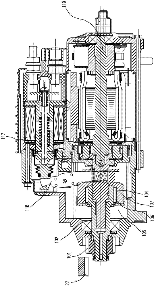
[0088] see Figures 2A-2C , Figure 2A It is a structural schematic diagram of the first embodiment of the present invention, Figure 2B for Figure 2A Enlarged view of the middle reduction mechanism, Figure 2C for Figure 2A Side view of the middle bracket. The gear on the armature shaft 20 on the electric motor 19 of the present embodiment is a sun gear 20a, and this sun gear 20a is the input end of motor power, and the power of the electric motor 19 is transmitted on the sun gear 20a, and the planetary gear 9 consists of one or A plurality of small gears as a group, the inner hole of the planetary gear 9 is interference fit with the bearing 21, the clearance fit between the bearing 21 and the gear pin 11, the gear pin 11 rotates freely in the bearing 21, the gear pin 11 and the planetary gear carrier 12 Relatively fixed, it can be realized by interference fit or other methods. The planetary gear carrier 12 is relatively fixed with the front support end cover 16 or mid...

no. 2 example

[0090] see image 3 , image 3 It is a structural schematic diagram of the second embodiment of the present invention. Compared with the first embodiment, the difference of this embodiment is that the deceleration ring gear 24 and the outer wall 6 of the one-way mechanism are integrated, which can be as follows Image 6 (in the first embodiment, the one-way mechanism outer wall 6 and the deceleration ring gear 24 are integrated parts enlarged view), it can also be as Figure 7(Second embodiment figure, middle one-way mechanism outer wall 6 and reduction mechanism ring gear 24 are set parts enlarged view as a whole), that is, the relatively fixed setting of the reduction gear ring gear 24 and one-way mechanism outer wall 6 shown, with pin To achieve the function of the one-way mechanism outer wall 6 and the deceleration ring gear 24 to transmit torque relatively fixedly, so as to reduce the difficulty of manufacturing larger parts, or realize the transmission of power from th...

Embodiment 4

[0094] see Figure 5 , Figure 5 It is a structural schematic diagram of the fourth embodiment of the present invention. In this embodiment, the principle of its power transmission structure is the same as that of the third embodiment, the difference is that the deceleration ring gear 24 of the deceleration mechanism and the inner wall 22 of the one-way mechanism are integral structural members of the same material, such as Figure 8 , it can also be assembled from two or more parts without relative rotation and movement, such as Figure 9 , as long as the output power of the deceleration ring gear 24 is transmitted to the partition wall 23 of the deceleration mechanism and then to the inner wall 22 of the one-way mechanism, the parts are arranged separately, which can adapt to the realization of different processing capabilities, reduce manufacturing difficulty, and reduce costs. The manner of power transmission between the reduction ring gear 24 and the inner wall 22 of th...


PUM


Abstract

The invention discloses a starter, a starting device of the starter and a one-way and speed reduction mechanism of the starting device. The starting device of the starter comprises a motor, an electromagnetic switch, a shifting fork, a speed reduction and one-way mechanism, an output shaft and a drive gear. The one-way and speed reduction mechanism comprises a one-way mechanism and a speed reduction mechanism. The speed reduction mechanism comprises a sun gear, a plurality of planet gears, a planet gear bracket, a speed reduction inner gear ring and a speed reduction isolation wall. The speed reduction inner gear ring is installed on the speed reduction isolation wall in a supported manner. The sun gear is arranged on an armature shaft. The planet gears are arranged on a plurality of gear pins of the planet gear bracket. The planet gears are engaged with gear teeth of the sun gear and the speed reduction inner gear ring at the same time. The one-way mechanism comprises a one-way mechanism outer wall, a one-way mechanism inner wall and a pin roller spring mechanism. A wedge-caulking hook face is arranged between the one-way mechanism outer wall and the one-way mechanism inner wall. The pin roller spring mechanism is arranged between the one-way mechanism outer wall and the one-way mechanism inner wall and located on the wedge-caulking hook face, and the one-way mechanism outer wall or the one-way mechanism inner wall is connected with the speed reduction isolation wall.

Description

technical field [0001] The invention relates to a starter for starting a vehicle engine, in particular to a starter including a one-way and deceleration mechanism and a starter with the starter. Background technique [0002] see Figure 1A , Figure 1A It is a structure diagram of the prior art noseless deceleration starter. It comprises an electric motor 119, a planetary reduction mechanism cooperating with the sun gear of the electric motor 119, a one-way mechanism 105, a drive pinion 101 on the gear shaft 102 integrated with the one-way mechanism, and an electromagnetic switch 117 and a relay. , the current flows into the electromagnetic switch 117 to pull the coil and hold the coil, and the iron core is driven to move towards the static iron core under the attraction of the magnetic field. With the movement of the iron core, the one-way mechanism and the driving pinion 101 are pulled out toward the direction of the engine ring gear 27 through the shift fork 118 . The e...

Claims


Application Information

Patent Timeline
Patent Type & Authority Patents(China)
IPC IPC(8): F02N11/00F02N15/06F16H1/32
Inventor 王霞胡立斌李启迪范福军
Owner PRESTOLITE ELECTRIC BEIJING
Why Eureka
Try Eureka