Magnetically driven horizontal vortex pump

A magnetic drive and vortex pump technology, which is applied in the direction of rotary piston pumps, rotary piston/swing piston pump combinations, rotary piston/swing piston pump components, etc., can solve the problem of plunger seal reliability decline, Energy waste, low life of wearing parts and other problems, to achieve a good sealing effect

Inactive Publication Date: 2016-02-17
兰州海兰德泵业有限公司
View PDF10 Cites 1 Cited by
  • Summary
  • Abstract
  • Description
  • Claims
  • Application Information

AI Technical Summary

Problems solved by technology

In actual operation, the oilfield pressure varies from high to low. If the pressure of the entire pipeline network is increased, pressure-reducing equipment needs to be added at the head of the low-pressure water injection well, which will cause waste of energy. Therefore, in order to reduce waste and reduce production input, solve some water injection orders. The problem of under-injection under high pressure in wells and blocks, the development of booster water injection pumps has become the focus of oilfield attention
[0003] In the prior art, there are mainly two types of booster water injection pumps: multi-stage centrifugal pump and high-pressure plunger pump. Among them, the multi-stage centrifugal pump has a relatively large displacement and a relatively low lift, which cannot meet the small flow requirements of certain blocks in the oil field. , high head requirements, especially the pressure at the inlet of the booster water injection pump is relatively high, and the shaft end seal adopts a mechanical seal, which cannot withstand the large inlet pressure, and it is difficult to achieve the seal; while the high-pressure plunger pump has a small flow rate and a high head. However, the high and low pressure alternating stress in the cylinder body will aggravate the fatigue damage, and the corrosion of the cylinder body by the medium containing chloride ions will cause the life of the wearing parts to be low and the cost of use will be high. Decreased plug seal reliability

Method used


Image

  • Magnetically driven horizontal vortex pump
  • Magnetically driven horizontal vortex pump

Examples


Embodiment Construction

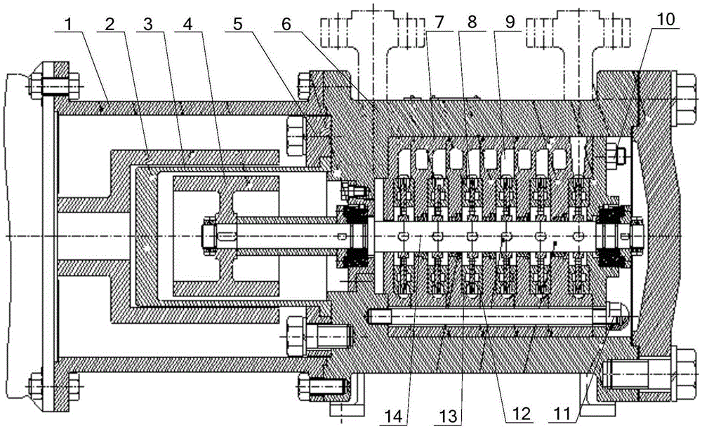
[0026] The invention provides a horizontal vortex pump driven by magnetic force, so as to meet the requirements of small flow rate and high head, and at the same time, it has good sealing performance, can meet the water injection requirements of oil wells with different pressures, is easy to disassemble and maintain, and has a low cost of use. low purpose.

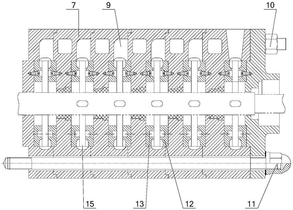
[0027] The following will clearly and completely describe the technical solutions in the embodiments of the present invention with reference to the accompanying drawings in the embodiments of the present invention. Obviously, the described embodiments are only some, not all, embodiments of the present invention. Based on the embodiments of the present invention, all other embodiments obtained by persons of ordinary skill in the art without making creative efforts belong to the protection scope of the present invention.

[0028] see figure 1 and figure 2 , figure 1 Schematic diagram of the structure of the magnetic driv...


PUM


Abstract

The invention discloses a magnetically driven horizontal vortex pump. The magnetically driven horizontal vortex pump comprises a pump housing with a water inlet and a water outlet, a rotor module, a stator module and a driving device, wherein the rotor module comprises a pump shaft which is arranged in the pump housing in a penetrating manner and is provided with two vortex wheels at least; the stator module comprises a pump unit consisting of at least two pump bodies arranged in the axial direction of the pump shaft, annular pump runners and a space transition runner used for communicating all the annular pump runners are arranged on the pump body, and the annular pump runners of the pump bodies at the two ends of the pump unit are respectively communicated with the water inlet and the water outlet of the pump housing; and the driving device is connected with the pump shaft through a magnetic coupling. The vortex pump has the characteristics of small flow and high lift. Through a spacer sleeve, an inner magnetic rotor and a medium are isolated from an outer magnetic rotor, so that full seal is realized. As long as the vortex wheels are increased or reduced according to requirements, the magnetically driven horizontal vortex pump can safely and reliably run so as to meet different water injecting requirements, and the performance range of the vortex pump is enlarged. Due to the adoption of a modular structure, the magnetically driven horizontal vortex pump is convenient to disassemble and maintain and low in use cost.

Description

technical field [0001] The invention relates to the technical field of water pumps, in particular to a horizontal vortex pump driven by magnetic force. Background technique [0002] With the increase of the production time of the oil well, the energy of the oil layer itself is continuously consumed, resulting in a continuous decrease in the pressure of the oil layer. In order to maintain or increase the pressure of the oil layer, achieve high and stable production of the oil field, and obtain a high recovery rate, the oil field must be injected with water. In actual operation, the oilfield pressure varies from high to low. If the pressure of the entire pipeline network is increased, pressure-reducing equipment needs to be added at the head of the low-pressure water injection well, which will cause waste of energy. Therefore, in order to reduce waste and reduce production input, solve some water injection orders. In order to solve the problem of under-injection under high pre...

Claims


Application Information

Patent Timeline
Patent Type & Authority Applications(China)
IPC IPC(8): F04C11/00F04C2/02F04C15/00H02K51/00
Inventor 豆耀锋张志广
Owner 兰州海兰德泵业有限公司
Why Eureka
Try Eureka