
Electromagnetic induction and USB dual-port charging control circuit and control flow

A charging control and electromagnetic induction technology, applied in battery circuit devices, circuit devices, electromagnetic wave systems, etc., can solve problems such as hidden dangers, safety, interface damage, etc., and achieve the effect of avoiding damage and avoiding power failure.

Inactive Publication Date: 2016-02-17
ZHONGHUAN TELCOM TECH
View PDF3 Cites 2 Cited by
  • Summary
  • Abstract
  • Description
  • Claims
  • Application Information

AI Technical Summary

Problems solved by technology

[0002] Today's chargers are divided into two types, one is without added Cable line, its appearance is small and easy to use, but one charger can only be used for one mobile phone; the other is added with Cable line, the shape is too large, but one The charger can charge two mobile phones, but wired charging can cause safety hazards during charging, receiving and making calls, surfing the Internet at work, and leisure and entertainment.
In daily life, work, and leisure, the power consumption of smart phones is relatively large, and power needs to be replenished at any time. Because the traditional wired charging mode requires repeated plugging and unplugging of the charging plug during use, it is easy to cause damage to the interface, resulting in failure. Charge
In modern society, the number of people with two mobile phones is gradually increasing, and the mode of only charging one mobile phone cannot meet the actual needs of today's users.
Making calls during charging, surfing the Internet at work, leisure and entertainment will have potential safety hazards. Wireless charging has become the direction of future development. A wireless charger for charging two mobile phones, so it is necessary to design a new USB charging control circuit

Method used


Image

  • Electromagnetic induction and USB dual-port charging control circuit and control flow
  • Electromagnetic induction and USB dual-port charging control circuit and control flow
  • Electromagnetic induction and USB dual-port charging control circuit and control flow

Examples


Embodiment 1

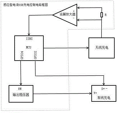
[0016] The utility model is an electromagnetic induction and USB dual-port charging control circuit and a control process, which uses a limited input power source (Adaptor) to calculate the power supply technology used by the additional device to supply the redundant available current under the condition of ensuring the normal use of the basic device. It is characterized in that it includes a charging sheet, a wireless charger body, and an auxiliary device. The auxiliary device includes a power output controller and a USB interface. The wireless charger body includes an operational amplifier, an output voltage regulator, a microprocessor, a resistor, a wireless charging system, and a wired charging system, the wireless charging system is connected to the operational amplifier through a resistor, the operational amplifier is connected to the microprocessor, the microprocessor is respectively connected to the output voltage regulator and the wired charging system, the wired chargi...

Embodiment 2

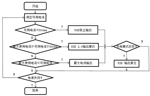
[0018] When in use, the charging mode of the USB interface is identified by detecting the voltage of the data line (D+, D-) of the USB interface, and it is judged whether the current state is the same as the previous state. When the mode changes, reset the output of the USB interface, and change the current into a voltage according to the OP-AMP and low resistance (about 20mA). Usually, the microprocessor MCU monitors the signal of its ISNS pin, and within the supported current, the microprocessor performs After calculation, the excess current is used in the wired charging system. When the current USB2.0Mode outputs 500mA, the wired charging system will perform low-speed charging; when the current does not perform wireless charging, wired charging will perform Full charging; when the current USB2.0Mode is less than 500mA , the system automatically cuts off wired charging.

Embodiment 3

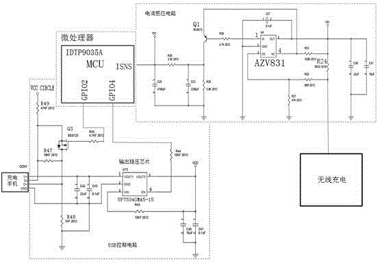
[0020] When a mobile phone is charged through a wireless charging device, and the charging current is above 1.3A, the charging current passes through R24 (0.022ohm) and the operational amplifier (AZV831) for signal conversion and comparison, and outputs high power from pin 1 of the operational amplifier (AZV831) Ping, acting on the base of Q1, so that Q1 is in the cut-off state, so the ISNS pin input of the microprocessor is a low-level signal, and the microprocessor makes the GPIO4 pin of the microprocessor output a low level through internal calculation. It is given to pin 4 of the enable terminal of the output voltage regulator chip (UP7534GMA5-15). phone charging.

[0021] When the wireless charging current is between 0.25A and 1.2A, the charging current is converted by R24 and the signal of the operational amplifier (AZV831), and the size is compared. The output pin 1 of the operational amplifier outputs a low level and acts on the base of Q1. Q1 is turned on, and the co...


PUM


Abstract

The invention provides an electromagnetic induction and USB dual-port charging control circuit and control flow. A limited input power source (Adaptor) is utilized, based on that normal use of basic devices is guaranteed, the power source technology used by a superfluous available current supply appending device is calculated. The flow is characterized by comprising a charging sheet, a wireless charger body and an auxiliary device, the auxiliary device comprises a power source output controller and a USB interface, the charger can realize wireless charging, so the charger can be used without repeatedly plugging and unplugging a charging plug, so the charger is prevented from being damaged by frequent plugging and unplugging.

Description

technical field [0001] The invention relates to a charging control circuit, in particular to an electromagnetic induction and USB dual-port charging control circuit and a control flow. Background technique [0002] Today's chargers are divided into two types, one is without added Cable line, its appearance is small and easy to use, but one charger can only be used for one mobile phone; the other is added with Cable line, the shape is too large, but one The charger can charge two mobile phones, but wired charging can cause safety hazards during charging, receiving and making calls, surfing the Internet at work, and leisure and entertainment. In daily life, work, and leisure, the power consumption of smart phones is relatively large, and power needs to be replenished at any time. Because the traditional wired charging mode requires repeated plugging and unplugging of the charging plug during use, it is easy to cause damage to the interface, resulting in failure. Charge. The ...

Claims


Application Information

Patent Timeline
Patent Type & Authority Applications(China)
IPC IPC(8): H02J7/00H02J17/00
Inventor 章嘉瑞李立周颖丽彭颖金镇弘金国珍
Owner ZHONGHUAN TELCOM TECH
Learn More