Pump

A high-pressure pump and piston technology, applied in the field of high-pressure pumps, can solve problems such as noise and reduced service life of high-pressure pumps, and achieve the effects of reducing impact, simplifying configuration, and reducing adverse consequences

Active Publication Date: 2016-02-17
ROBERT BOSCH GMBH
View PDF6 Cites 4 Cited by
  • Summary
  • Abstract
  • Description
  • Claims
  • Application Information

AI Technical Summary

Problems solved by technology

[0003] The high-pressure pump known from DE 10 2009 003 054 A1 has the disadvantage that during operation, due to the displacement of the volume of the piston in the drive mechanism chamber in which the drive shaft is arranged, due to the delivery characteristics or additionally due to the movement of the drive element Body waves, which are emitted into a further low-pressure system or into another low-pressure region and cause an increased pressure load there
This can later lead to noise or also to a reduced service life of the high-pressure pump

Method used


Image

  • Pump
  • Pump
  • Pump

Examples


Embodiment Construction

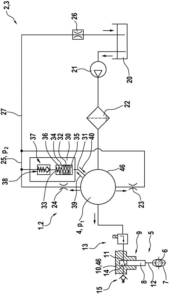
[0026] figure 1 According to a first exemplary embodiment, a high-pressure pump 1 of a fuel injection system 2 with a low-pressure circuit 3 is shown in a schematic illustration. The high-pressure pump 1 can be used in particular for air-compressed self-igniting internal combustion engines or hybrid-compression externally ignited internal combustion engines. Furthermore, the high-pressure pump 1 can also be configured as a hydraulic pump for other hydraulic applications.

[0027] The high-pressure pump 1 has a low-pressure chamber 4 and a drive 5 . During operation, pressure pulses are generated in the low-pressure chamber 4 by the drive 5 . In this exemplary embodiment, the low-pressure chamber 4 is formed by a drive mechanism chamber in which the shaft 6 with a plurality of cams 7 is at least partially arranged. A plurality of cams 7 of the shaft 6 serve to drive a pump piston 8 of a pump assembly 9 of the high-pressure pump 1 . Here, a section of a cylinder head 10 is s...


PUM


Abstract

The invention relates to a high-pressure pump (1) which serves in particular for fuel injection systems of internal combustion engines, comprising a low pressure chamber (4) configured as a power unit chamber (4) and a drive (5) which is disposed at least partially in the low pressure chamber (4). In operation pressure pulses are generated in the low pressure chamber (4) by the drive unit (5). A damping device (30) is provided which on the one hand is coupled to the low pressure chamber (4) and on the other hand is connected to a low pressure level (25) which in operation is located below a pressure (p1) in the low pressure chamber (4). The damping device (30) has a piston which is displaceable in a piston bore (33) and which not only is acted upon by the pressure (p1) in the low pressure chamber (4) against a spring force of a spring element (36) but also delimits a vapour chamber (34) in the piston bore (33). Furthermore the damping device (30) has a pressure relief means (37) which connects the vapour chamber (34) at least intermittently to the low pressure level (25).

Description

technical field [0001] The invention relates to a pump, in particular a high-pressure pump for fuel injection systems or hydraulic applications. In particular, the invention relates to the field of diesel pumps, petrol pumps and hydraulic pumps. Background technique [0002] A high-pressure pump for a fuel injection system of an air-compressed self-igniting internal combustion engine is known from DE 10 2009 003 054 A1. The known high-pressure pump has a pump assembly and a drive shaft, wherein the drive shaft includes a cam assigned to the pump assembly. The pump assembly includes rollers that roll on the rolling surfaces of the cams. The drive shaft is supported on a bearing bracket in the housing part of the high-pressure pump. The reciprocating motion of the piston is realized when the high-pressure pump is running, so that the fuel under high pressure is delivered to the common rail. Here, the drive shaft rotates about an axis during operation of the high-pressure p...

Claims


Application Information

Patent Timeline
Patent Type & Authority Applications(China)
IPC IPC(8): F04B11/00F02M59/10F02M59/44F02M55/04F04B53/00
CPCF02M55/04F02M59/102F02M59/44F02M2200/03F02M2200/09F02M2200/31F02M2200/315F04B1/0404F04B1/0408F04B11/0033
Inventor A·克勒
Owner ROBERT BOSCH GMBH
Why Eureka
Try Eureka