Large-scale biological negative electrode microbial fuel cell stack apparatus

A fuel cell stack and bio-cathode technology, which is applied in the field of water treatment, can solve the problem of no bio-cathode microbial fuel cell for wastewater treatment, and achieve the effects of improving long-term stability, large processing capacity and reducing costs

Active Publication Date: 2016-02-24
INST OF URBAN ENVIRONMENT CHINESE ACAD OF SCI
View PDF6 Cites 13 Cited by
  • Summary
  • Abstract
  • Description
  • Claims
  • Application Information

AI Technical Summary

Problems solved by technology

At present, microbial fuel cells have attracted much attention because of their short hydraulic retention time, low sludge volume, suitable temperature, and reusable energy. However, due to the need for expensive catalysts in the cathode, there are currently reports on the application of pilot-scale microbial fuel cells to treat wastewater. Fewer, and no pilot-scale biocathode microbial fuel cells have been reported to treat wastewater

Method used


Image

  • Large-scale biological negative electrode microbial fuel cell stack apparatus

Examples


Embodiment approach 1

[0013] Embodiment 1: Device installation

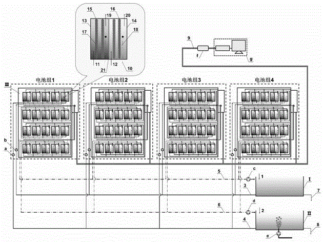
[0014] device according to figure 1 The schematic diagram shown is installed: the anion exchange membrane 21 divides the microbial fuel cells in the battery pack 1 and the battery pack 2 into an anode chamber 13 and a cathode chamber 14, and the cation exchange membrane 21 divides the microbial fuel cells in the battery pack 3 and the battery pack 4 The fuel cell is divided into an anode chamber 13 and a cathode chamber 14, wherein the anion exchange membrane 21 and the cation exchange membrane 21 adopt a non-toxic ion exchange membrane with a transmittance of 94%, a thickness of 0.3 mm, and a burst strength ≥ 0.5 MPa; A carbon felt with a thickness of 5-6 mm is loaded into the chamber 13 as the anode 15, and a carbon felt with a thickness of 5-6 mm is loaded into the cathode chamber 14 as the cathode 16. The anode 15 distributes anaerobic microorganisms 17 with a thickness of 50-70 μm, and the cathode 16 The aerobic microorganisms 1...

Embodiment approach 2

[0015] Embodiment 2: device operation

[0016] After the installation of the device is completed, in the anode pool I, biochemically treatable organic wastewater is added from the anode pool inlet 1 to make it in an anaerobic state with a dissolved oxygen concentration lower than 0.2mg / L, and through the anolyte inflow pipe 3 and the anode circulation When the pump a is lifted, it is injected into the anode chamber 13 from the water inlet 11 of the anode chamber. The organic matter in the wastewater is initially degraded under the action of anaerobic microorganisms 17. At the same time, the electrons generated by the degradation of pollutants are transferred to the anode 15. Discharged from the anode chamber water outlet 19, merged with the same level of microbial fuel cell anode chamber 13 and used as the next level and as the water intake of the next stage microbial fuel cell anode chamber 13, flows into the anode outflow pipe 5 after four stages of degradation, and passes th...


PUM

PropertyMeasurementUnit
thicknessaaaaaaaaaa
bursting strengthaaaaaaaaaa
thicknessaaaaaaaaaa

Abstract

The invention belongs to the technical field of water treatment, and relates to a large-scale biological negative electrode microbial fuel cell stack apparatus. The apparatus comprises a plurality of biological negative electrode microbial fuel cells; organic matters in organic waste water are removed by anaerobe from a positive electrode; inorganic carbon in inorganic carbon source waste water is removed by aerobe in the negative electrode; the electric energy is recycled, wherein the microbial fuel cell pack comprises a positive electrode chamber, a negative ion/positive ion exchange membrane, a negative electrode chamber, a water path, and an external circuit; the waste water containing organic pollutants enters the positive electrode chamber; the pollutants are subjected to microbial anaerobic decomposition to generate electrons, the electrons are transmitted to the positive electrode, and then the electrons are transmitted to the negative electrode through the external circuit for realizing electricity generation. The apparatus is simple, efficient, free from a chemical catalyst, safe, reliable, green, environment-friendly, compact in structure, high in handling capacity, and convenient in actual applications.

Description

technical field [0001] The invention belongs to the technical field of water treatment and relates to a large biocathode microbial fuel cell stack device. The device uses anaerobic microorganisms in the anode to remove organic matter in organic wastewater, uses aerobic microorganisms in the cathode to remove inorganic carbon in inorganic carbon source wastewater, and recovers electric energy. Background technique [0002] Microbial fuel cell is a new type of sewage treatment technology developed rapidly in recent years. It generally consists of three parts: anode chamber, separator membrane and cathode chamber. Among them, the anode chamber has the function of treating organic wastewater; the cathode chamber has the function of removing inorganic carbon and nitrification reaction through aeration; the intermediate separation membrane can use anion membrane or cation membrane according to specific conditions. Different reactions occur in the cathode and anode chambers: in th...

Claims


Application Information

Patent Timeline
Patent Type & Authority Applications(China)
IPC IPC(8): H01M8/16H01M8/249
CPCH01M8/04186H01M8/249Y02E60/50
Inventor 赵峰郑志勇陈立香吴冉冉
Owner INST OF URBAN ENVIRONMENT CHINESE ACAD OF SCI
Why Eureka
Try Eureka