Combined heat dissipating device provided with fins and foam heat conduction structure
A technology of heat dissipation device and heat conduction structure, applied in electrochemical generators, electrical components, circuits, etc., can solve the problem of insufficient heat transfer effect enhancement, small effective contact area between foam metal and battery, and no reduction of contact interface air gap mechanism. and other problems, to achieve the effect of improving low thermal conductivity, reducing battery temperature rise, and overcoming large porosity
- Summary
- Abstract
- Description
- Claims
- Application Information
AI Technical Summary
Problems solved by technology
Method used
Image
Examples
Embodiment 1
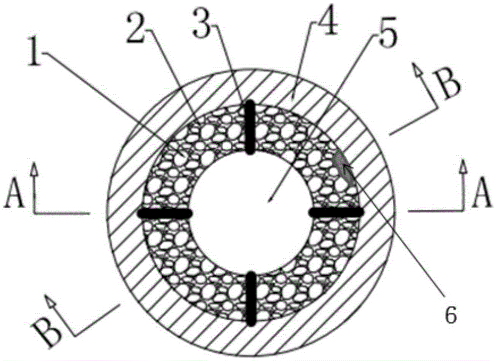
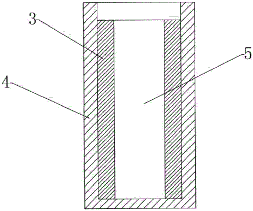
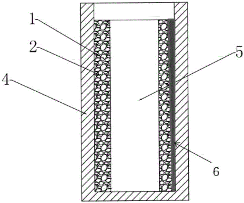
[0031] A composite heat dissipation device with fins and foam heat conduction structure, used to assist the heat dissipation of the battery cell 5, its structure is as follows figure 1 , figure 2 with image 3 As shown, the composite heat dissipation device includes a casing sleeve 4 sleeved outside the battery cell 5, the material of the casing sleeve 4 is aluminum, and a foam structure 2 is filled between the casing sleeve 4 and the battery cell 5, and the foam structure 2 The height is similar to that of the battery cell 5, with a height of 60mm and a thickness of 2mm. The material of the foam structure 2 is porous copper foam with a pore density of 10PPI and a porosity of 70%. The foam structure 2 is filled with a melting point of 30~ Phase change material 1 at 33°C, phase change material 1 is paraffin, and four fins 3 separating the foam structure 2 are arranged between the shell sleeve 4 and the battery cell 5 to enhance heat transfer, and the fins 3 are rectangular ...
Embodiment 2
[0033]A composite heat sink with fins and a foam heat conduction structure, used to assist the heat dissipation of the battery cell 5, the composite heat sink includes a shell sleeve 4 sleeved outside the battery cell 5, and the material of the shell sleeve 4 is copper , the foam structure 2 is filled between the shell sleeve 4 and the battery cell 5, the height of the foam structure 2 is similar to the height of the battery cell 5, the height is 100mm, and the thickness is 7mm. The material of the foam structure 2 is 100PPI, pore density Porous aluminum foam with a rate of 99%. The foam structure 2 is filled with a phase-change material 1 with a melting point of 45-48°C. The phase-change material 1 is paraffin. Four fins 3 separating the foam structure 2 are used to enhance heat transfer. The fins 3 are rectangular fins whose height is similar to that of the battery cell 5. The height is 100 mm and the thickness is 1.5 mm. The material of the fins 3 is copper. , the two sides...
Embodiment 3
[0035] A composite heat sink with fins and a foam heat conduction structure, used to assist the heat dissipation of the battery cell 5, the composite heat sink includes a shell sleeve 4 sleeved outside the battery cell 5, and the material of the shell sleeve 4 is aluminum , the foam structure 2 is filled between the shell sleeve 4 and the battery cell 5, the height of the foam structure 2 is similar to the height of the battery cell 5, the height is 80 mm, and the thickness is 4 mm. Porous graphite foam with a rate of 85%. The foam structure 2 is filled with a phase-change material 1 with a melting point of 78-80°C. The phase-change material 1 is paraffin. Four fins 3 separating the foam structure 2 are used to enhance heat transfer. The fins 3 are rectangular fins whose height is similar to that of the battery cell 5. The height is 80mm and the thickness is 0.9mm. The material of the fins 3 is aluminum , the two sides of the fin 3 are closely attached to the shell sleeve 4 an...
PUM
| Property | Measurement | Unit |
|---|---|---|
| thickness | aaaaa | aaaaa |
| melting point | aaaaa | aaaaa |
| thickness | aaaaa | aaaaa |
Abstract
Description
Claims
Application Information
 - R&D
- Intellectual Property
- Life Sciences
- Materials
- Tech Scout
- Unparalleled Data Quality
- Higher Quality Content
- 60% Fewer Hallucinations
Browse by: Latest US Patents, China's latest patents, Technical Efficacy Thesaurus, Application Domain, Technology Topic, Popular Technical Reports.
© 2025 PatSnap. All rights reserved.Legal|Privacy policy|Modern Slavery Act Transparency Statement|Sitemap|About US| Contact US: help@patsnap.com


