
Multi-energy complementary power generation system and power supply distribution method

A power generation system and distribution method technology, applied in the field of electric power, can solve the problems of multiple batteries, high cost, and inability to form a stable energy guarantee system with multi-energy complementarity, so as to achieve the effect of reducing consumption, reducing dependence, and improving energy utilization efficiency

Active Publication Date: 2016-02-24
青岛索迷尔能源科技有限公司
View PDF6 Cites 11 Cited by
  • Summary
  • Abstract
  • Description
  • Claims
  • Application Information

AI Technical Summary

Problems solved by technology

The main defect of the existing utilization mode is: the direct access of discontinuous power to the grid is still "garbage power"; if it is not connected to the grid, it can only be supplied to the user through the battery, which cannot form a stable energy security system with multi-energy complementarity, and requires more battery, expensive

Method used


Image

  • Multi-energy complementary power generation system and power supply distribution method

Examples


Embodiment 1

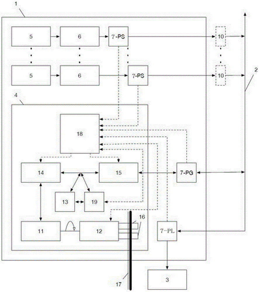
[0023] Such as figure 1 As shown, it is a schematic diagram of the power generation system when the power grid exists. The power generation system 1 is connected to the power grid 2 and the power load 3. The power grid 2 provides three-phase alternating current according to a given frequency F, and the power load terminal 3 includes one or Multiple users, using three-phase alternating current with frequency F.

[0024] The multi-energy complementary power generation system 1 includes a continuous generator set 4 and a discontinuous generator set, and the continuous generator set 4 includes a generator 11, an engine 12 driving the generator 11, a first inverter 14, and a second inverter 15 and an electrical storage device 13, the energy storage device 13 is a storage battery, such as a certain number of lead storage batteries, used to store DC electric energy, the first inverter 11 is connected between the generator 11 and the electrical storage device 13, and uses When the el...

Embodiment 2

[0039] In this embodiment, the power generation system 1 operates in an off-grid state, that is, the grid does not exist. The power generation system is the same as that in Embodiment 1, and will not be repeated here.

[0040] The power supply optimization distribution method of the multi-energy complementary power generation system includes the following steps:

[0041] 1), the power measuring device 7 connected to the back end of the second and third inverters and the front end of the user load measures the power supply PG of the continuous generator set, the power supply PS of the discontinuous generator set, and the power consumption PL of the user load, And return the measured data to the controller 18;

[0042] 2) The controller judges whether the power supply PS of the discontinuous generating set can meet the power load 3. When the power grid does not exist, PN_out and PN_in are 0, so the power balance formula 1-1 is simplified as: PS+PG=PL( 1-2), according to the fo...


PUM


Abstract

The invention discloses a multi-energy complementary power generation system and a power supply distribution method. The multi-energy complementary power generation system includes a continuous generator set and a discontinuous generator set, the continuous generator set is a conventional system that utilizes a generator to generate electricity, the discontinuous generator set is a system that utilizes various renewable resources to generate electricity, and the continuous generator set and the discontinuous generator set work in a complementary mode, thereby providing stable and continuous power supply. The method provided by the invention preferably utilizes electric power output generated by the discontinuous generator set, i.e., by local renewable energy sources, when the discontinuous generator set does not generate electricity or generated electricity is insufficient, electricity is supplemented by the continuous generator set, an on-line UPS function is achieved, and dependency on traditional energy is greatly reduced.

Description

technical field [0001] The invention relates to a multi-energy complementary power generation system and a power supply distribution method, belonging to the technical field of electric power. Background technique [0002] As we all know, in some areas that cannot be covered by the grid, that is, areas where there is no grid or the grid is insufficient to meet the electricity demand, such as remote rural areas, tourist attractions, islands, border posts, etc., there is a huge demand for small and medium power generation systems. The investment in laying power grid projects in these areas is huge. Using traditional methods such as diesel generators to generate electricity, the cost of power production is too high. Making full use of various renewable energy sources in these areas and combining them with traditional energy sources (such as diesel, natural gas, liquefied petroleum gas, etc.) to produce electricity while recycling waste heat from power generation is undoubtedly ...

Claims


Application Information

Patent Timeline
IPC IPC(8): H02J7/34H02J7/35H02J3/46F24J2/04
CPCY02E10/44H02J7/34F24S10/00H02J3/46H02J7/35
Inventor 包春光杨辰昊
Owner 青岛索迷尔能源科技有限公司
Features
  • Generate Ideas
  • Intellectual Property
  • Life Sciences
  • Materials
  • Tech Scout
  • Unparalleled Data Quality
  • Higher Quality Content
  • 60% Fewer Hallucinations
Learn More