
Compact type gasbag polishing precession mechanism

A kind of airbag polishing and compact technology, which is applied in the direction of surface polishing machine tools, grinding/polishing equipment, grinding drive devices, etc. It can solve the problems of easy deformation of the swing arm, large space occupation, high cost, etc., and reduce the supporting equipment of machine tools device, increase structural rigidity, and save space

Active Publication Date: 2016-03-02
XIAMEN UNIV
View PDF9 Cites 2 Cited by
  • Summary
  • Abstract
  • Description
  • Claims
  • Application Information

AI Technical Summary

Problems solved by technology

The precession mechanism is a necessary mechanism for precession polishing. The precession mechanism currently used in processing is a precision airbag polishing tool system disclosed in the applicant's patent CN201210568640.3. The whole is in the form of an isosceles right triangle , this structure occupies a large space and has a large mass, which makes the overall structure of the machine tool larger, and the stiffness of the precession mechanism is also lower. The swing arm is prone to deformation during the process of pressing down the airbag, which affects the processing quality
At the same time, the airbag tool needs to be connected with an inflatable device to maintain the air pressure inside the airbag in real time. In order to ensure the airtightness of the airbag, the structure of the machine tool spindle is relatively complicated, and an air pressure device needs to be installed during processing, which is costly

Method used


Image

  • Compact type gasbag polishing precession mechanism
  • Compact type gasbag polishing precession mechanism

Examples


Embodiment Construction

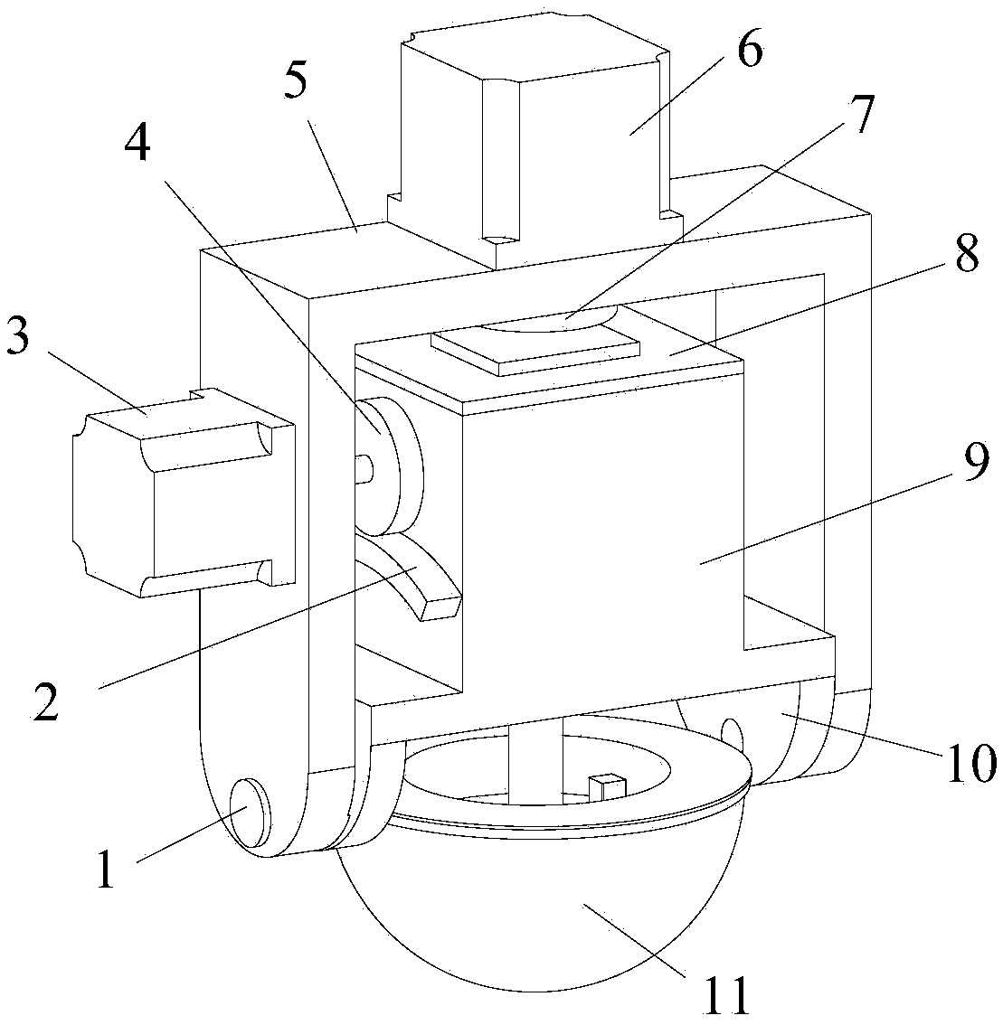
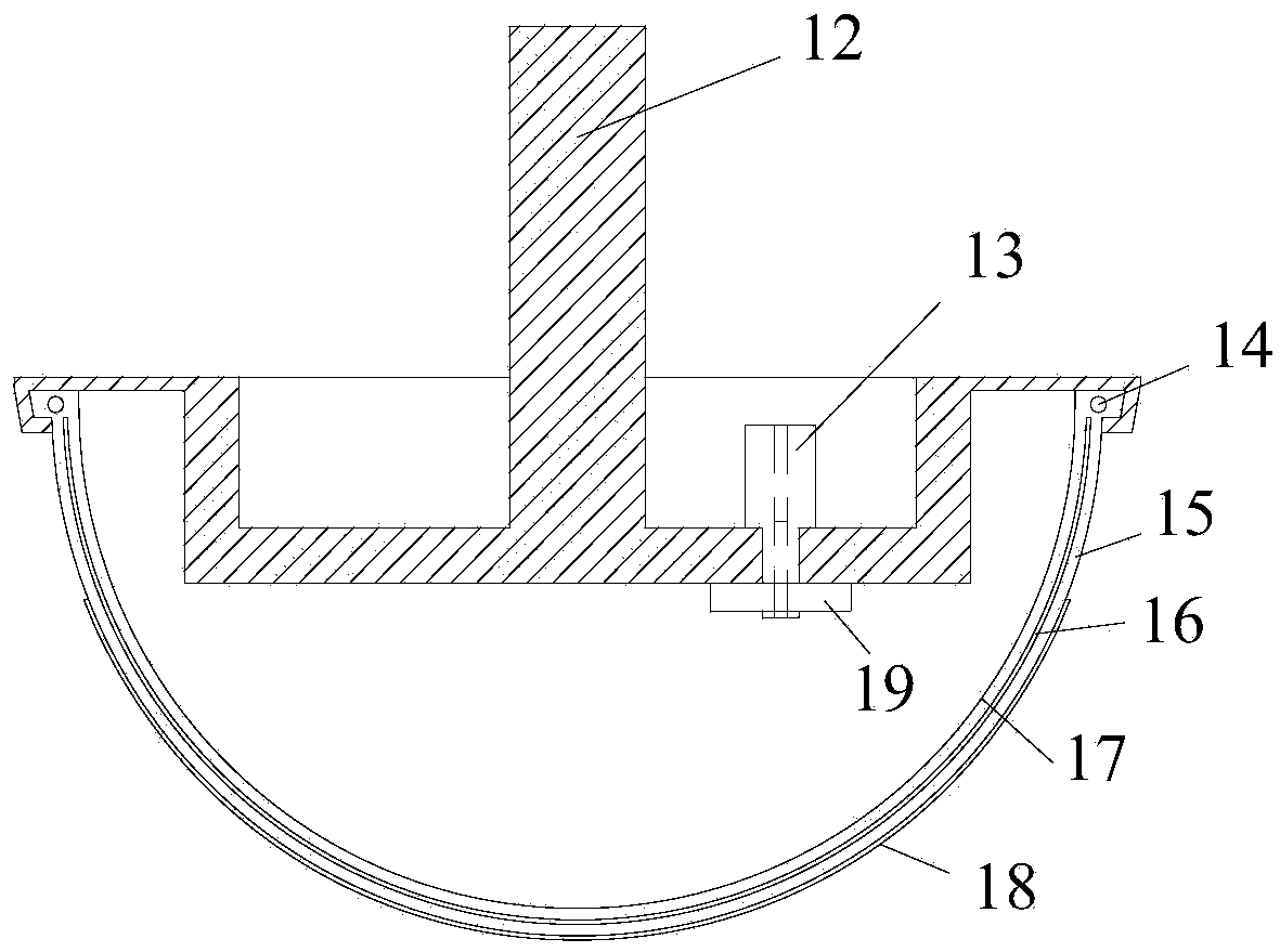
[0016] Such as figure 1 and 2 As shown, the embodiment of the present invention is provided with a horizontal axis 1, an arc rack 2, a horizontal axis motor 3, a gear 4, a swing arm 5, a vertical axis motor 6, a vertical axis 7, an end cover 8, a headstock 9, and a headstock Swing arm 10, airbag tool 11, spindle motor, coupling and bearing.

[0017] Described swing arm 5 is vertically installed, and vertical shaft motor 6 is vertically installed on swing arm 5 tops, controls swing arm 5 to rotate, and headstock 9 is nestedly installed in swing arm 5 inside, and headstock swing arm 10 passes horizontal axis 1 and The lower end of the swing arm 5 is connected, the arc rack 2 is installed on the left side of the headstock 9, the horizontal axis motor 3 is vertically fixed on the left side of the swing arm 5, and the gear 4 and the arc rack 2 installed on the motor shaft end of the horizontal axis motor 3 Engaging; the main shaft motor is a hollow structure, the main shaft motor...


PUM


Abstract

The invention discloses a compact type gasbag polishing precession mechanism and relates to gasbag polishing. The compact type gasbag polishing precession mechanism is provided with horizontal shafts, an arc rack, a horizontal shaft motor, a gear, a swing arm, a vertical shaft motor, a vertical shaft, an end cover, a spindle box, spindle box swing arms, a gasbag tool, a spindle motor, a coupling and a bearing. The swing arm is installed vertically. The vertical shaft motor is vertically installed at the top of the swing arm and controls the swing arm to rotate. The spindle box is installed inside the swing arm in an inlaid mode. The spindle box swing arms are connected with the lower end of the swing arm through the horizontal shafts. The arc rack is installed on the left side of the spindle box. The horizontal shaft motor is vertically fixed to the left side of the swing arm. The gear installed at the motor shaft end of the horizontal shaft motor is engaged with the arc rack. The spindle motor is of a hollow structure and is installed inside the spindle box. The gasbag tool is located at the bottom of the spindle box and connected with a spindle of the spindle motor through the coupling. According to the compact type gasbag polishing precession mechanism, a tire structure is adopted, inflation is easy, the precession mechanism can be separated from a pneumatic supply, the number of matched devices of a machine tool is reduced, and the spindle structure of the machine tool is simplified.

Description

technical field [0001] The invention relates to airbag polishing, in particular to a compact airbag polishing precession mechanism. Background technique [0002] With the development of industrial technology, engineering requires higher and higher surface precision of optical components, which has reached the micro-nano level. At present, the finishing of optical components mainly adopts the grinding and polishing method. Among the many polishing methods, airbag polishing can not only ensure the good fit between the polishing head and the surface of the workpiece to be polished, but also has high polishing efficiency, so it is widely used. . [0003] Airbag polishing mostly adopts precession polishing, which can form a chaotic surface texture on the surface of the workpiece and obtain a good surface quality. The precession mechanism is a necessary mechanism for precession polishing. The precession mechanism currently used in processing is a precision airbag polishing tool ...

Claims


Application Information

Patent Timeline
Patent Type & Authority Applications(China)
IPC IPC(8): B24B29/00B24B47/12B24D99/00
CPCB24B29/00B24B47/12B24D99/00
Inventor 王振忠杨旭
Owner XIAMEN UNIV
Learn More