
Feedback control method, feedback control method based control method for asymmetric half bridge type flyback converter, and realization circuits for two methods

A flyback converter, feedback control technology, applied in control/regulation systems, output power conversion devices, DC power input conversion to DC power output and other directions, can solve the problem of poor load regulation, large number of components, line voltage problems such as poor regulation rate, to achieve the effect of high output voltage accuracy

Active Publication Date: 2016-03-02
MORNSUN GUANGZHOU SCI & TECH
View PDF4 Cites 30 Cited by
  • Summary
  • Abstract
  • Description
  • Claims
  • Application Information

AI Technical Summary

Problems solved by technology

[0006] In order to achieve a high isolation withstand voltage between the input and output, the existing IGBT drive power supply mostly adopts an open-loop scheme, and the most direct disadvantages of the open-loop scheme include: high output voltage at no-load, poor load regulation; output voltage Varies with input voltage, poor line voltage regulation
[0007] Other driving power schemes include two-stage architecture, the first stage realizes isolation and step-down, and the second stage realizes voltage regulation. This scheme can achieve higher isolation withstand voltage level, good line voltage regulation rate, and higher output voltage Accuracy, but the disadvantages of this solution are also obvious, the solution is complex, the design is difficult; the number of components is large, and the cost is unacceptable

Method used


Image

  • Feedback control method, feedback control method based control method for asymmetric half bridge type flyback converter, and realization circuits for two methods
  • Feedback control method, feedback control method based control method for asymmetric half bridge type flyback converter, and realization circuits for two methods
  • Feedback control method, feedback control method based control method for asymmetric half bridge type flyback converter, and realization circuits for two methods

Examples


no. 1 example

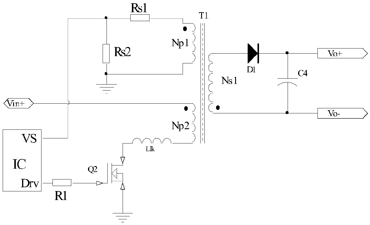
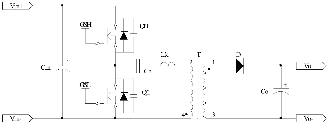
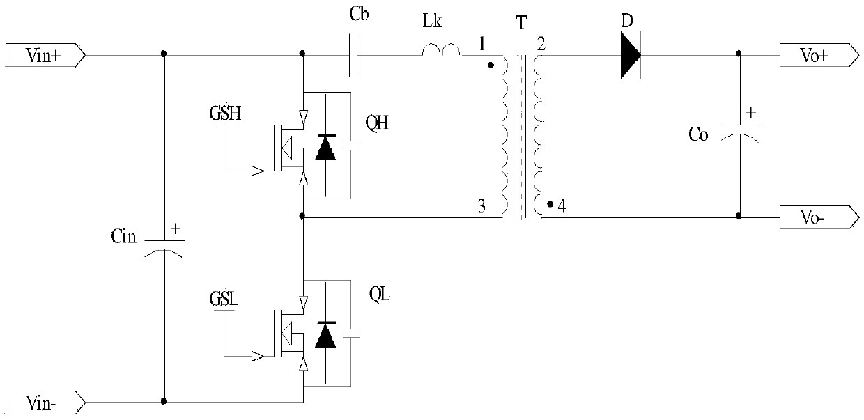
[0047] Figure 5 Shows a functional block diagram of a switching converter according to an embodiment of the present invention, an asymmetric half-bridge flyback primary side feedback control converter under non-complementary DCM conditions, including a flyback circuit and a primary side feedback circuit, the flyback circuit includes a primary side circuit And the secondary side output rectification filter circuit. The primary side circuit is formed by connecting the DC blocking capacitor C3, the main switch MOS tube QH, the clamp switch MOS tube QL and the primary winding Np1 of the transformer. The secondary side output rectification filter circuit is formed by the secondary The side winding Ns1 is connected with the capacitor C4 and the diode D1. The specific connection relationship is that the input voltage Vin+ is connected to the drain of the N-MOS transistor QH, and the source of the N-MOS transistor QH is connected to the primary winding N of the flyback transformer T1 v...


PUM


Abstract

The invention aims to realize that a control mode of primary side feedback is added into an asymmetric half bridge type flyback converter in a non-complementary DCM mode. For the asymmetric half bridge type flyback converter working in the non-complementary DCM mode, primary side inductance is released and is not clamped by an output end at the moment of finishing primary side excitation energy resetting. At the time, the primary side inductance, resonant capacitance, leakage inductance, and parasitic capacitance between the drain and the source of an MOS transistor start resonance oscillation; and at the moment of oscillation starting, a voltage between the drain and the source of the MOS transistor forms an "inflection point", voltages on two ends of the primary side inductance reflect voltage changes of the output end, voltages ontwo ends of an auxiliary winding have similar changes, an oscillation starting direction is just opposite to the direction of the voltages on the two ends of the primary side inductance due to a dotted terminal winding relationship, and if the inflection point is detected through the auxiliary winding and inflection point information is transmitted to a controller, the detection and control of an output voltage can be realized. Compared with the prior art, relatively high output voltage precision, linear adjustment rate and load adjustment rate of the converter can be ensured; and meanwhile, zero voltage switching (ZVS) of a primary side switch tube can be realized, the working frequency of the converter can be increased, the efficiency of the converter can be improved, and the volume of a complete machine is reduced.

Description

Technical field [0001] The invention belongs to a switching converter of an electric energy conversion device, and particularly relates to an asymmetric half-bridge flyback converter and its feedback control technology. Background technique [0002] With the development of science and technology, some power supplies require adjustable charging current and output voltage. When accurate output voltage is required, secondary side feedback (commonly used optocoupler + TL431 feedback and control method) is used, that is, output terminal feedback, which is equivalent to Add a current detection circuit on the secondary side. This solution can guarantee a higher output voltage accuracy, but the product design is difficult, the cost is high, the isolation withstand voltage is low, and the shortcomings are obvious. [0003] In recent years, electronic devices such as smart phones and IPADs that integrate functions such as entertainment and communication have taken the world by storm. This ...

Claims


Application Information

Patent Timeline
Patent Type & Authority Applications(China)
IPC IPC(8): H02M3/338
CPCH02M3/3385
Inventor 金若愚周耀彬王志燊
Owner MORNSUN GUANGZHOU SCI & TECH
Learn More