Graphite evaporator for concentration by evaporation and automatic control system thereof

A technology of automatic control system and graphite evaporator, which is applied in the direction of control/regulation system, non-electric variable control, evaporation, etc., can solve the problems of heat exchange efficiency reduction, evaporator damage, low degree of automation, etc., to improve corrosion resistance High pressure performance, enhanced corrosion resistance, and high steam utilization

Active Publication Date: 2016-03-16
PINGDINGSHAN XINRUIDA NEW MATERIAL TECH CO LTD
View PDF8 Cites 2 Cited by
  • Summary
  • Abstract
  • Description
  • Claims
  • Application Information

AI Technical Summary

Problems solved by technology

In the traditional graphite evaporator, there is only one steam inlet, and a large amount of high-temperature steam will rise up when entering the evaporator, resulting in uneven distribution of steam in the upper and lower parts of the evaporator, which will lead to uneven heat distribution and heat transfer. The efficiency is reduced, and in the case of a sudden increase in the steam pressure, if the steam pressure is not controlled, the evaporator will be damaged due to the sudden increase in the steam pressure; in addition, the steam entering the traditional evaporator is injected If the steam passes through the heat exchange holes of the graphite heat exchange block, the utilization rate of the steam is reduced and it is easy to cause the graphite heat exchange block to burst; in the existing graphite evaporator, the graphite evaporator is often in a humid working environment, and the outer wall of the shell is easy to Leakage caused by rust, the condensed liquid in the evaporator cannot be discharged in time and is vaporized repeatedly, which reduces the utilization rate of steam, and also causes excessive humidity in the evaporator to cause damage to the graphite heat exchange block and other parts; in addition, the existing The graphite evaporator has a low degree of automation, a large amount of manual operation, a small safety factor, and a correspondingly high cost

Method used


Image

  • Graphite evaporator for concentration by evaporation and automatic control system thereof

Examples


Embodiment Construction

[0040] All the features disclosed in this specification, or all disclosed methods or steps in the process, except for mutually exclusive features and / or steps, can be combined in any manner.

[0041] Any feature disclosed in this specification (including any additional claims and abstract), unless specifically stated, can be replaced by other equivalent or alternative features with similar purposes. That is, unless otherwise stated, each feature is just one example of a series of equivalent or similar features.

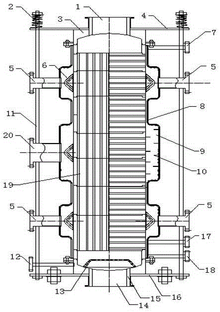
[0042] Such as figure 1 As shown, figure 1 A graphite evaporator for evaporation and concentration of the present invention is shown. Several layers of graphite heat exchange blocks 19 are arranged in the shell 8. The upper end of the shell 8 is provided with a material outlet 1 and the lower end is provided with a material inlet 14. Condensate inlet 17, condensate outlet 18, and sewage outlet 12 are provided on both sides of the lower part of the casing 8. The condensat...


PUM


Abstract

The invention provides a graphite evaporator for concentration by evaporation. The graphite evaporator comprises a housing, a waveform heat insulating layer is spread on an inner wall of the housing, a corrosion preventing composite layer is spread on an outer wall of the housing, and the housing is made from stainless steel; the upper part, the middle part and the lower part of the housing are separately provided with a loop of steam distributor, sides of each of the steam distributors at the upper part and the lower part of the housing are provided with steam inlets, a steam inlet passage is arranged at one side of the steam distributor in the middle part of the housing, automatic control systems are connected to the steam inlets, and a steam outlet is arranged above one side of the steam inlet at the upper part of the housing; several U-shaped grooves and lateral through holes are arranged at the outside of graphite heat exchange blocks, and places between every two layers of the graphite heat exchange blocks are sealed with fluororubber. The graphite evaporator has the advantages of improved steam utilization rate, enhanced corrosion resistance, high temperature resistance and high pressure resistance, prolonged service life, and excellent performance; and automatic control is realized at the same time. The invention also comprises an automatic control system for controlling the graphite heat exchanger for concentration by evaporation.

Description

Technical field [0001] The invention relates to a graphite evaporator, in particular to a graphite evaporator used for evaporation and concentration and an automatic control system thereof. Background technique [0002] Graphite evaporators are widely used in pharmaceutical, chemical and other industries. Because graphite has the characteristics of high temperature resistance, corrosion resistance, high pressure resistance, and good thermal conductivity, it is commonly used to evaporate and concentrate acid and alkaline waste liquids or liquid materials. In the traditional graphite evaporator, there is only one steam inlet. A large amount of high-temperature steam will rise up when entering the evaporator, resulting in uneven steam distribution in the upper and lower parts of the evaporator, which will result in uneven heat distribution and heat exchange. The efficiency is reduced, and in the case of a sudden increase in steam pressure, if the steam pressure is not controlled, th...

Claims


Application Information

Patent Timeline
Patent Type & Authority Applications(China)
IPC IPC(8): B01D1/00G05D27/02
Inventor 夏烬楚
Owner PINGDINGSHAN XINRUIDA NEW MATERIAL TECH CO LTD
Why Eureka
Try Eureka