Gear burr removing system with real-time monitoring function

A real-time monitoring and gear technology, which is applied to gear tooth manufacturing devices, belts/chains/gears, gear teeth, etc., to achieve the effects of ensuring meshing performance, high economic benefits, and simple structure

Inactive Publication Date: 2016-03-16
CHONGQING GUANGDA MACHINERY FACTORY CO LTD
View PDF0 Cites 4 Cited by
  • Summary
  • Abstract
  • Description
  • Claims
  • Application Information

AI Technical Summary

Problems solved by technology

This kind of gear has high load-carrying capacity and efficiency, but it is not as easy to manufacture as the involute gear, and needs to be further improved

Method used


Image

  • Gear burr removing system with real-time monitoring function
  • Gear burr removing system with real-time monitoring function

Examples


Embodiment 1

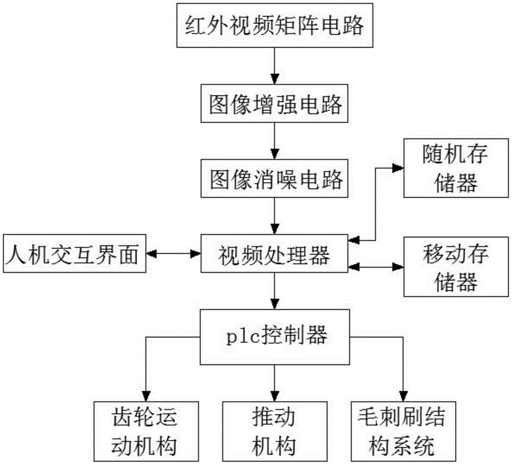
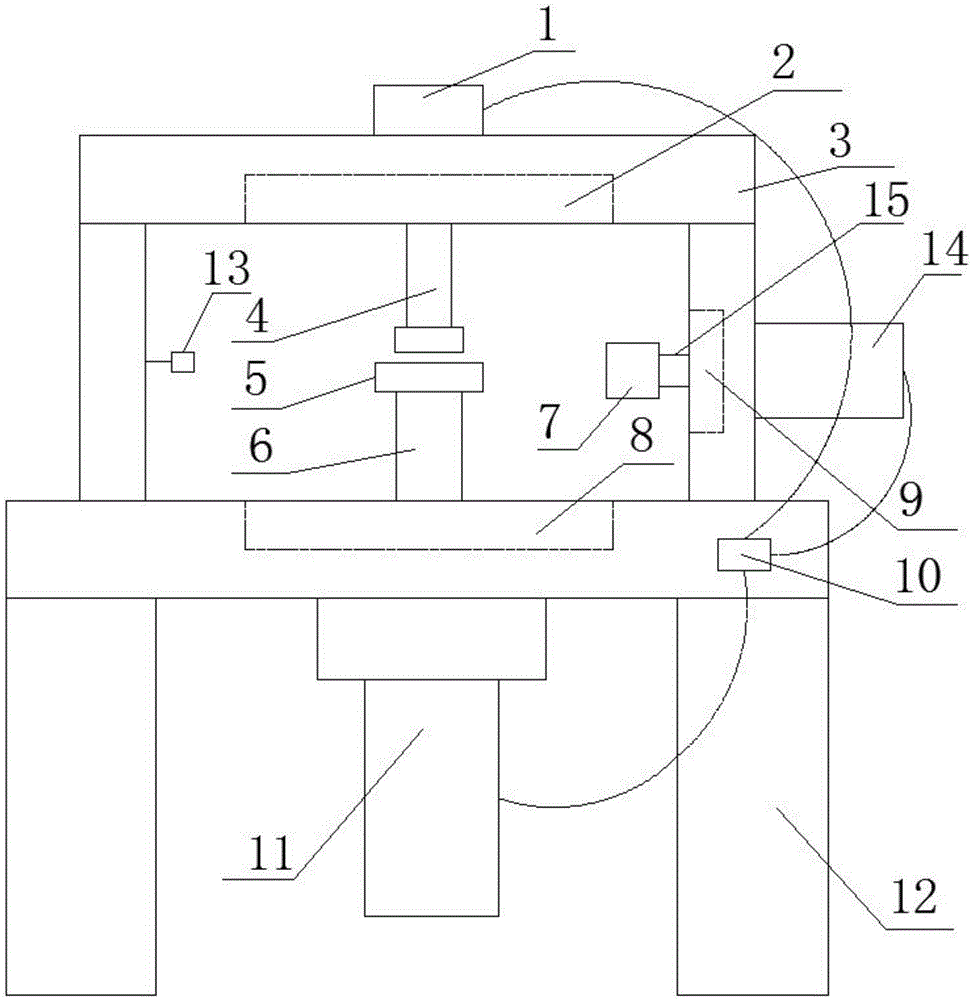
[0031] A system for deburring gears that can be monitored in real time. It can record the entire deburring process during gear surface deburring processing, and can record the gear image information extracted from the working process recording information in real time. Combining the comparison results of qualified gear image information preset in the video processor to formulate a new working strategy for the entire system, so as to achieve the purpose of automatic monitoring of gear deburring work, such as figure 1 , figure 2 As shown, the following structure is specially set up: including the system body and the control device 10 arranged on the system body, the system body is provided with an upper support system 3 and a lower support system 12, and the upper support system 3 is fixed on the lower part On the upper platform of the bracket system 12, the control device 10 is arranged on the lower bracket system 12; a gear movement mechanism 11 is arranged on the lower brack...

Embodiment 2

[0035] This embodiment is further optimized on the basis of the above-mentioned embodiments. In order to better realize the present invention, the gear to be deburred can be deburred by using the burr brush structure system under the cooperation of the gear movement mechanism and the pushing mechanism. ,Such as figure 1 , figure 2 As shown, the following structure is particularly provided: the rotating shaft 6 of the gear movement mechanism 11 runs through the upper table of the lower bracket system 12; the rotating shaft 4 of the pushing mechanism 1 runs through the upper table of the upper bracket system 3, and the rotating shaft 6 Coaxial with rotating shaft 4.

Embodiment 3

[0037] This embodiment is further optimized on the basis of any of the above-mentioned embodiments. Further, in order to better realize the present invention, the noise in the video signal after signal enhancement can be cleared so that the restored image is clearer, such as figure 1 , figure 2 As shown, the following structure is particularly provided: an image denoising circuit is also provided between the image enhancement circuit and the video processor.


PUM

PropertyMeasurementUnit
lengthaaaaaaaaaa
diameteraaaaaaaaaa

Abstract

The invention discloses a gear burr removing system with the real-time monitoring function. The system comprises a system body and a control device arranged on the system body. The system body is provided with an upper support system and a lower support system. The lower support system is provided with a gear movement mechanism. A push mechanism is further arranged on the upper table top of the upper support system. A burr brush structure system is arranged on a side support of the upper support system. An infrared video matrix circuit, an image enhancement circuit, a video processor and a plc are arranged in the control device. The plc is connected with the gear movement mechanism, the push mechanism and the burr brush structure system. When burrs on the surface of a gear are removed, the whole burr removing work process can be recorded, and a new work strategy of the whole system can be made according to a result obtained through comparing gear image information shot in real time with qualified gear image information preset in the video processor.

Description

technical field [0001] The invention relates to the technical field of gear manufacturing, in particular to a real-time monitoring system for removing burrs from gears. Background technique [0002] Gear, a mechanical element with teeth on the rim that continuously mesh to transmit motion and power. The application of gears in transmission has appeared very early. At the end of the 19th century, the principle of generative gear cutting method and special machine tools and cutting tools using this principle appeared one after another. With the development of production, the stability of gear operation was paid more attention. [0003] In the west, in 300 BC, the ancient Greek philosopher Aristotle, in "Mechanical Problems", just elaborated the problem of using bronze or cast iron gears to transmit rotary motion. The famous Greek scholars Aristotle and Archimedes have both studied gears. The famous Greek inventor Gutisibios evenly inserted pins on the edge of the circular pl...

Claims


Application Information

Patent Timeline
Patent Type & Authority Applications(China)
IPC IPC(8): B23F19/00B23F23/00B23Q17/20B23Q17/24
CPCB23F19/00B23F23/00B23Q17/20B23Q17/2409
Inventor 王彩虹
Owner CHONGQING GUANGDA MACHINERY FACTORY CO LTD
Why Eureka
Try Eureka