
Semi-lumped microwave band-pass filtering circuit and filter

A filtering circuit and microwave band technology, applied in the field of filtering, can solve problems such as limitations, and achieve the effects of low insertion loss, high stop band suppression, and high squareness

Inactive Publication Date: 2016-03-16
成都新欣神风电子科技有限公司
View PDF8 Cites 2 Cited by
  • Summary
  • Abstract
  • Description
  • Claims
  • Application Information

AI Technical Summary

Problems solved by technology

Traditional filter circuits and implementations are severely limited in high frequency / RF bands

Method used


Image

  • Semi-lumped microwave band-pass filtering circuit and filter
  • Semi-lumped microwave band-pass filtering circuit and filter
  • Semi-lumped microwave band-pass filtering circuit and filter

Examples


Embodiment Construction

[0026] The present invention will be further described in detail below in conjunction with examples, but the embodiments of the present invention are not limited thereto.

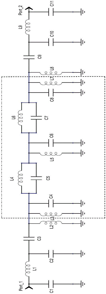
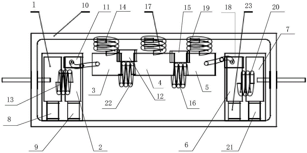
[0027] Such as figure 1 as shown, figure 1 It shows a schematic structural diagram of a semi-lumped microwave bandpass filter circuit according to an embodiment of the present invention, a semi-lumped microwave bandpass filter circuit, which consists of an elliptic function filter circuit (the part inside the dotted line) and a high-low pass matching envelope Composition (the part outside the dotted line), specifically including the first capacitor C1, the second capacitor C2, the third capacitor C3, the fourth capacitor C4, the fifth capacitor C5, the sixth capacitor C6, the seventh capacitor C7, the eighth capacitor C8, the The ninth capacitor C9, the tenth capacitor C10, the eleventh capacitor C11, the first inductor L1, the second inductor L2, the fourth inductor L4, the fifth inductor L5, the sixth in...


PUM


Abstract

The invention discloses a semi-lumped microwave band-pass filtering circuit and a filter. The semi-lumped microwave band-pass filtering circuit and the filter are based on a design theory of a conventional elliptic function filter, and input and output ports are subjected to high-and-low pass matching, so that the problem of gentle out band rejection of the elliptic function filter is solved. The semi-lumped microwave band-pass filtering circuit and the filter are mainly used for rejecting clutter interference, meanwhile, have better phase congruency compared with band-pass filtering devices with other structures, and can be widely applied to antennas used in communication systems.

Description

technical field [0001] The invention relates to the field of filter technology, in particular to a semi-lumped microwave bandpass filter circuit and filter. Background technique [0002] In recent years, a series of studies on filter circuits have been carried out at home and abroad. Through continuous improvement and transformation of traditional filter circuits, many research results have been achieved in terms of filter performance and implementation forms. Widely used in power amplifier front-end and radar antenna feeder, it provides an effective solution to solve the system out-of-band noise. [0003] As the operating frequency continues to increase, the capacitance and inductance values ​​of the band-pass filter synthesized through the low-pass prototype filter continue to decrease, and the influence of the distribution parameters becomes more and more obvious. Traditional filtering circuits and implementations are severely limited in high frequency / RF bands. Aiming ...

Claims


Application Information

Patent Timeline
Patent Type & Authority Applications(China)
IPC IPC(8): H03H7/01
CPCH03H7/0161
Inventor 何小东吴孟珈李勇明付强王柯人
Owner 成都新欣神风电子科技有限公司
Learn More