Hydraulic pressure suspension polishing device with controllable fluid boundary

A fluid boundary and polishing device technology, applied in the field of precision polishing, to improve the surface processing effect, ensure uniformity, and improve processing accuracy

Active Publication Date: 2016-03-23
ZHEJIANG UNIV OF TECH
View PDF7 Cites 4 Cited by
  • Summary
  • Abstract
  • Description
  • Claims
  • Application Information

AI Technical Summary

Problems solved by technology

[0004] The purpose of the present invention is to solve the problem of controllable fluid boundary in the existing non-contact suspension polishing device, and provides a hydrodynamic pressure suspension polishing device with controllable fluid boundary. For the problem of fluid boundary sealing during suspension polishing, the polishing device optimizes the relative positional relationship between the polishing disc and the container, improves the stability of fluid dynamic pressure, and improves processing efficiency

Method used


Image

  • Hydraulic pressure suspension polishing device with controllable fluid boundary
  • Hydraulic pressure suspension polishing device with controllable fluid boundary
  • Hydraulic pressure suspension polishing device with controllable fluid boundary

Examples


Embodiment Construction

[0022] The present invention will be further described below in conjunction with accompanying drawing:

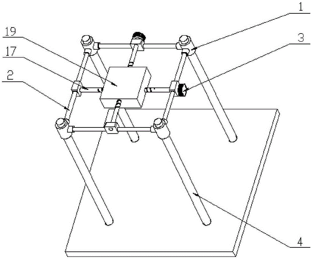
[0023] like figure 1 as shown, figure 1 It is a three-dimensional diagram of the fine-tuning system structure of a hydrodynamic pressure suspension polishing device with controllable fluid boundary in the present invention. The planar movement of the plate 19, that is, the adjustment of the polishing disc 9 to move to the geometric center of the polishing liquid container 8, prepares for the rear lifting device to adjust the position of the polishing liquid container 8 in the Z direction.

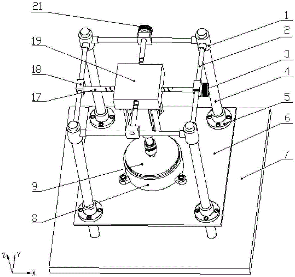
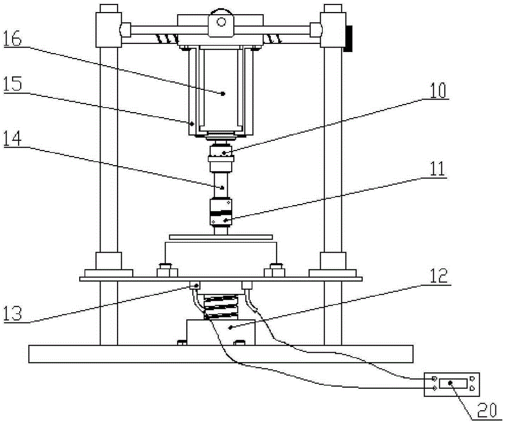
[0024] figure 2 and image 3 It is a structural schematic diagram of a hydraulic suspension polishing device with controllable fluid boundaries. The main components include a horizontal worktable 7, a spiral lifting column 12, a polishing liquid container 8, a polishing disc 9, and a servo motor 16. The polishing liquid container 8 is fixed on On the support plate 6, the load cell 1...


PUM


Abstract

The invention discloses a hydraulic pressure suspension polishing device with a controllable fluid boundary. The hydraulic pressure suspension polishing device comprises a horizontal workbench, a polishing system, a lifting system, a fine adjustment system and a pressure detection system. The polishing system comprises a polishing disc, a polishing liquid container, a first coupling, a spindle, a second coupling, a motor support and a serve motor. The hydraulic pressure suspension polishing device has the advantages that a gap between the polishing disc and the wall of the polishing liquid container is small, a good condition is provided for forming good hydraulic pressure, and accordingly the machining efficiency and the surface machining effect can be improved; a polishing tool is separated from a workpiece, and the workpiece is immersed in the polishing liquid, so that the abrasion of the polishing tool is relieved easily, and negative effects caused by friction heat in the polishing process are reduced; the polishing disc is directly driven by the servo motor, error accumulation caused by complex transmission links is avoided, and the machining precision is improved.

Description

technical field [0001] The invention relates to the field of precision polishing, more specifically, a hydraulic suspension polishing device with controllable fluid boundary is designed. Background technique [0002] Ultra-precision polishing is a non-contact polishing process, and the surface of the workpiece is precisely polished by a hydraulic suspension polishing device. Precision and ultra-precision machining technology and manufacturing automation are two major fields of advanced manufacturing technology. Precision engineering, fine engineering and nanotechnology are the frontier of modern manufacturing technology and the foundation of future manufacturing technology. Ultra-precision machining is an emerging comprehensive processing technology. It integrates advanced technological achievements such as modern machinery, electronics, measurement and materials, which greatly improves the current machining accuracy, greatly improves the performance of products and improves...

Claims


Application Information

Patent Timeline
Patent Type & Authority Applications(China)
IPC IPC(8): B24B29/00B24B49/16B24B55/00
CPCB24B29/00B24B49/165B24B55/00
Inventor 洪滔谢重孙白冰姬孟托
Owner ZHEJIANG UNIV OF TECH
Why Eureka
Try Eureka