
Mist spraying dyeing machine

A dyeing machine and dyeing tube technology, applied in the field of spray dyeing machines, can solve problems such as uneven dyeing, poor effect, and increased production costs of enterprises, and achieve the goals of increasing spraying area, reducing dye liquor sewage, and enhancing adhesion Effect

Active Publication Date: 2016-03-23
SUZHOU DABANG TEXTILE CO LTD
View PDF7 Cites 11 Cited by
  • Summary
  • Abstract
  • Description
  • Claims
  • Application Information

AI Technical Summary

Problems solved by technology

Although dip-dyeing can improve the washing fastness, since dip-dyeing is to put the whole piece of fabric to be dyed into a large dyeing tank, there will definitely be stacking of fabrics, and there will be problems of uneven dyeing. In the tank, all the fabrics to be dyed need to be submerged in it, and the amount of dyeing solution required is also large. When it is not used up, it is easy to cause waste, and the resulting discharge of sewage, waste gas and waste residue is also serious, which is not conducive to environmental protection. Increase the production cost of the enterprise, leading to the decline of the competitiveness of the enterprise
[0004] Spray dyeing is to spray dye into the fabric to be dyed. Although it can solve the problem of dye waste, the effect of spray dyeing is not very good. There are poor washing fastness, different light fastness, and uneven spray dyeing, resulting in The dye cannot penetrate into the fibers of the inner layer, resulting in uneven dyeing

Method used


Image

  • Mist spraying dyeing machine

Examples


Embodiment Construction

[0020] In order to deepen the understanding of the present invention, the present invention will be further described below in conjunction with the embodiments and accompanying drawings. The embodiments are only used to explain the present invention and do not constitute a limitation to the protection scope of the present invention.

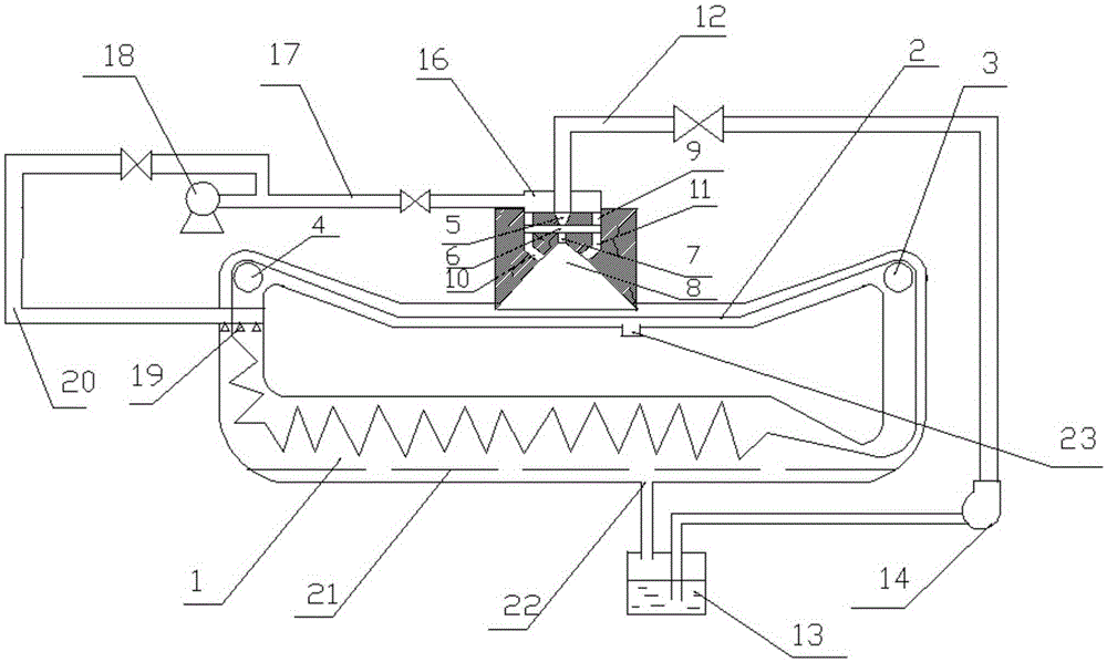
[0021] see figure 1 As described above, a dyeing machine for dyeing fabrics includes a U-shaped fabric storage pipe 1 and a dyeing pipe 2 horizontally arranged above the fabric storage pipe, and the two ends of the dyeing pipe are respectively inclined upward at 10-30 degrees relative to the horizontal direction. The extension is connected with the two ends of the U-shaped fabric storage pipe, and the two ends of the U-shaped fabric storage pipe are connected with the two ends of the dyeing pipe. The first rotating roller 3 for driving the fabric from the fabric storage pipe into the dyeing pipe and for Drive the fabric out of the dyeing pipe and...


PUM


Abstract

The invention discloses a mist spraying dyeing machine. The mist spraying dyeing machine comprises a U-shaped fabric storage tube and a dyeing tube which is horizontally arranged above the fabric storage tube, the two ends of the dyeing tube extend upward in an inclined mode relative to the horizontal direction and are communicated with the two ends of the U-shaped fabric storage tube respectively, and the communication positions between the two ends of the U-shaped fabric storage tube and the two ends of the dyeing tube are provided with a first rotating roller and a second rotating roller respectively, wherein the first rotating roller is used for driving a fabric out of the fabric storage tube to enter the dyeing tube, the second rotating roller is used for driving the fabric out of the dyeing tube to enter the fabric storage tube, and an aerosol spray head which vertically sprays dye liquor to the fabric is arranged on the upper portion of a horizontal section of the dyeing tube. By means of the mist spraying dyeing machine, the fabric is dyed more uniformly, meanwhile, the bath ratio is lowered, and dye liquor sewage is remarkably reduced.

Description

technical field [0001] The invention belongs to printing and dyeing equipment, in particular to a spray dyeing machine. Background technique [0002] There are generally two types of fabric dyeing techniques known in the industry, one is dip-dyeing and the other is spray-dyeing. [0003] In exhaust dyeing, a large amount of dyeing liquor is first placed in a large dyeing tank, and the cloth to be dyed is put into the large dyeing tank, and then the cloth to be dyed is dyed through dip dyeing. Although dip-dyeing can improve the washing fastness, since dip-dyeing is to put the whole piece of fabric to be dyed into a large dyeing tank, there will definitely be stacking of fabrics, and there will be problems of uneven dyeing. In the tank, all the fabrics to be dyed need to be submerged in it, and the amount of dyeing solution required is also large. When it is not used up, it is easy to cause waste, and the resulting discharge of sewage, waste gas and waste residue is also ser...

Claims


Application Information

Patent Timeline
IPC IPC(8): D06B1/02D06B23/20
CPCD06B1/02D06B3/24D06B23/20
Inventor 叶建新
Owner SUZHOU DABANG TEXTILE CO LTD
Learn More