Full-automatic laser tunnel section convergence instrument and measuring method

A fully automatic, convergence instrument technology, applied in measurement devices, instruments, optical devices, etc., can solve the problems of unable to ensure that the tunnel convergence deformation microwave always hits the target, unable to meet the full-section tunnel convergence deformation, unable to achieve long-term cross-section monitoring and other problems , to achieve the effect of light weight, avoiding manual on-site operation and quick installation

Active Publication Date: 2016-03-23
SHANGHAI UNDERGROUND ARCHITECTURAL DESIGN & RESEARCH INSTITUTE +1
View PDF13 Cites 28 Cited by
  • Summary
  • Abstract
  • Description
  • Claims
  • Application Information

AI Technical Summary

Problems solved by technology

The above three patent documents combine a single handheld laser rangefinder with a mechanical structure, which can only measure the deformation of the horizontal diameter or vertical diameter of the tunnel from point to point. This measurement mode cannot meet the needs of convergent deformation of the full-section tunnel.
[0005] Patent document CN103776359A discloses a tunnel convergence sensor based on microwave ranging, but this sensor needs to set a target on the inner wall of the tunnel. However, in long-term monitoring, it is impossible to ensure that the convergence deformation of the tunnel can make the microwave always hit the target
Patent document CN104613887A discloses a section settlement convergence analysis instrument, which includes a front and rear vertical measurement laser system and a semicircular surface laser ranging system, which can

Method used


Image

  • Full-automatic laser tunnel section convergence instrument and measuring method
  • Full-automatic laser tunnel section convergence instrument and measuring method
  • Full-automatic laser tunnel section convergence instrument and measuring method

Examples


Embodiment Construction

[0046] The specific implementation manners of the present invention will be described in detail below in conjunction with the accompanying drawings.

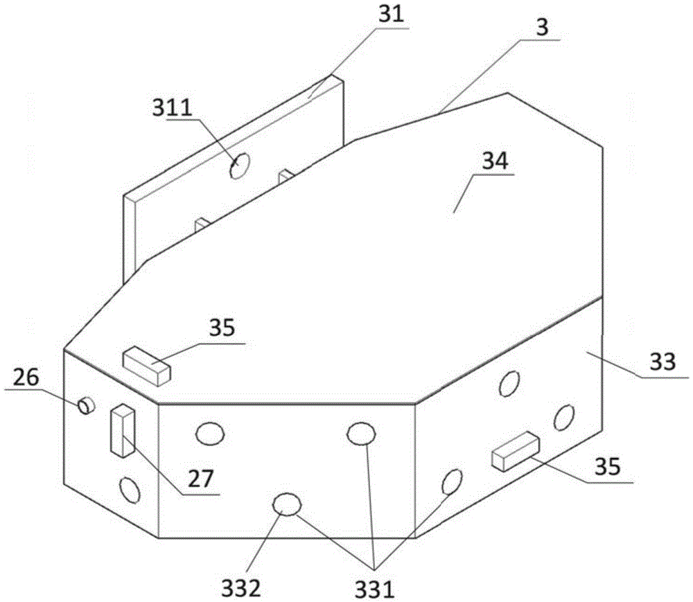
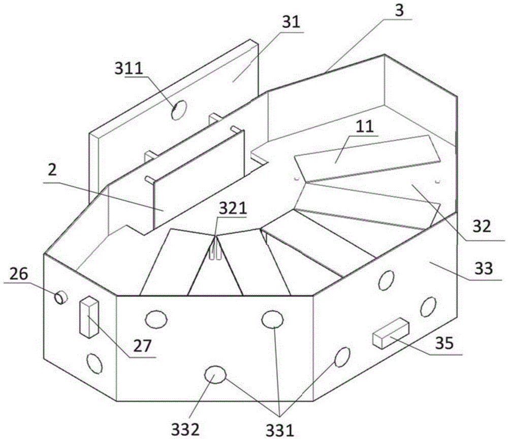
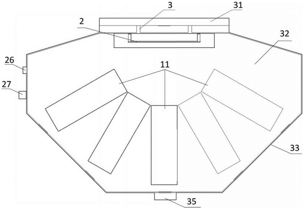
[0047] See figure 1 , figure 2 , image 3 , a fully automatic laser tunnel section convergent instrument, including three subsystems: a laser ranging system, a collection and communication system 2, and an installation and fixing system 3.

[0048] The laser ranging system includes several laser ranging modules 11, and the laser ranging module 11 adopts any one of a phase laser ranging sensor, a laser radar ranging sensor, and a laser triangular ranging sensor. The measurement axes of all laser ranging modules meet at one point in reverse, and the measurement range of the laser ranging module and the angle between each laser ranging module can be designed and adjusted according to specific engineering requirements, so that the measurement range can meet 0-360° Full coverage.

[0049] Such as Figure 4 As shown, the acquisi...


PUM


Abstract

The invention discloses a full-automatic laser tunnel section convergence instrument and a measuring method. The full-automatic laser tunnel section convergence instrument comprises a laser ranging system, an acquisition and communication system (2) and a mounting and fixing system (3), wherein the laser ranging system comprises a plurality of laser ranging modules (11); the acquisition and communication system (2) comprises a central processing module, a data acquisition module, a data storage module, a data communication module, a power management module, a power interface (26) and a data interface (27); the mounting and fixing system (3) comprises a pedestal (31), a core plate (32), a frame plate (33), a cover plate (34) and an inclinometer (35); and the laser ranging modules (11) are fixed on the core plate (32), each laser ranging module (11) is connected with the data acquisition module through a data line, and the laser ranging modules (11) and the core plate (32) are arranged within the frame plate (33). The full-automatic laser tunnel section convergence instrument can be mounted on a tunnel vault or side wall conveniently, and achieve full-automatic tunnel section multi-point convergence monitoring and data transmission.

Description

technical field [0001] The invention relates to the field of tunnel deformation monitoring, in particular to a fully automatic laser tunnel section convergence instrument, which is suitable for long-term monitoring of the convergence deformation of railway and highway tunnel sections. Background technique [0002] In the construction and operation stages of tunnels and underground projects, the convergence deformation of tunnel sections is an important monitoring content. In the construction stage, the convergence deformation of the section reflects the stress state and stability of the tunnel structure and surrounding rock and soil under unloading conditions; while in the operation and maintenance stage, it reflects the performance evolution of the tunnel structure, which is the key to judging the safety and security of the tunnel structure. An important basis for operation and maintenance. [0003] The most commonly used tunnel section convergence measurement device is th...

Claims


Application Information

Patent Timeline
IPC IPC(8): G01B11/16
CPCG01B11/16
Inventor 顾沉颖段创峰巴雅吉呼熊诚吴惠明戴子枢何晓施永泉赵峻李章林
Owner SHANGHAI UNDERGROUND ARCHITECTURAL DESIGN & RESEARCH INSTITUTE
Why Eureka
Try Eureka