
Laser-displacement-sensor-based journal axle center measurement apparatus, and measurement and calibration methods thereof

A technology of laser displacement and measuring device, which is applied to measuring devices, optical devices, instruments, etc., can solve the problems of high measurement accuracy, small measuring range, and high measurement environment requirements, and achieves large measuring range, high measurement accuracy, and convenient operation. sexual effect

Inactive Publication Date: 2016-03-23
TIANJIN UNIV
View PDF6 Cites 24 Cited by
  • Summary
  • Abstract
  • Description
  • Claims
  • Application Information

AI Technical Summary

Problems solved by technology

Image measurement is limited by the optical depth of field, and the measurement accuracy is poor; the measurement force of the contact probe is easy to cause scratches on the journal surface of the measured shaft parts, and it is not convenient for on-machine measurement in the production line; the measurement of the pneumatic quantity measurement method High precision but small range, and high requirements for the measurement environment

Method used


Image

  • Laser-displacement-sensor-based journal axle center measurement apparatus, and measurement and calibration methods thereof
  • Laser-displacement-sensor-based journal axle center measurement apparatus, and measurement and calibration methods thereof
  • Laser-displacement-sensor-based journal axle center measurement apparatus, and measurement and calibration methods thereof

Examples


Embodiment Construction

[0051] The laser displacement sensor-based journal shaft center measurement device and measurement calibration method of the present invention will be described in detail below with reference to the embodiments and the accompanying drawings.

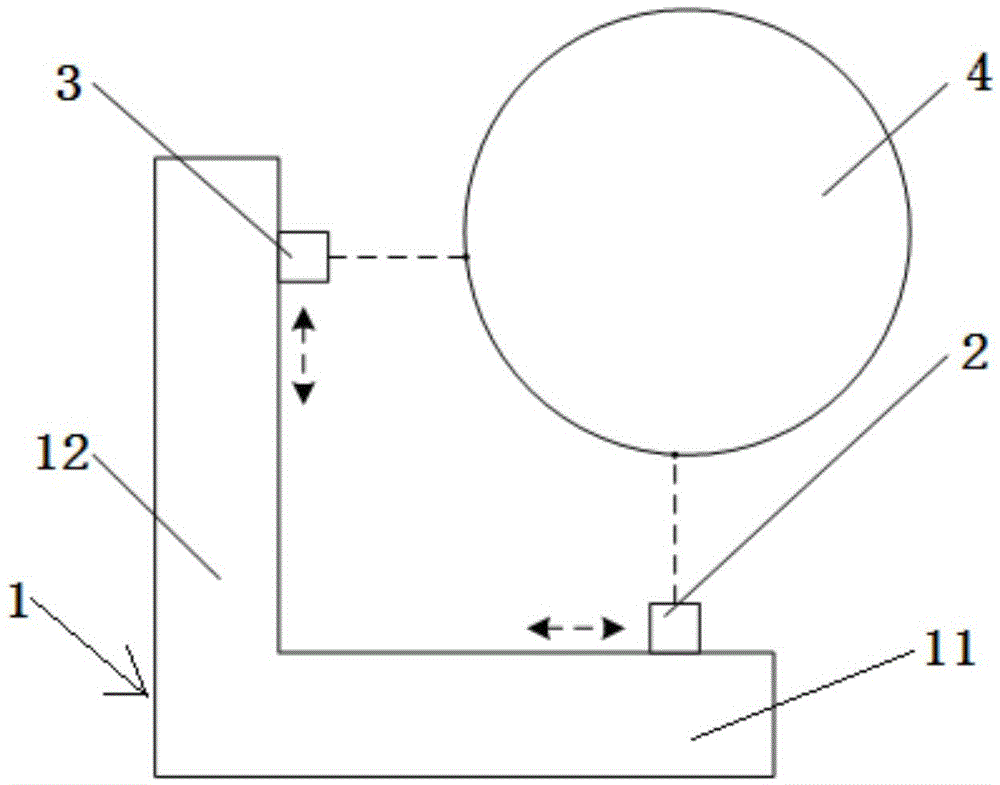
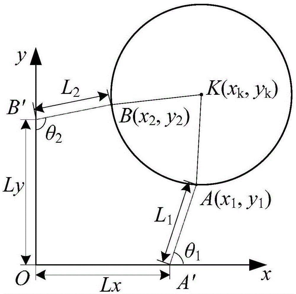
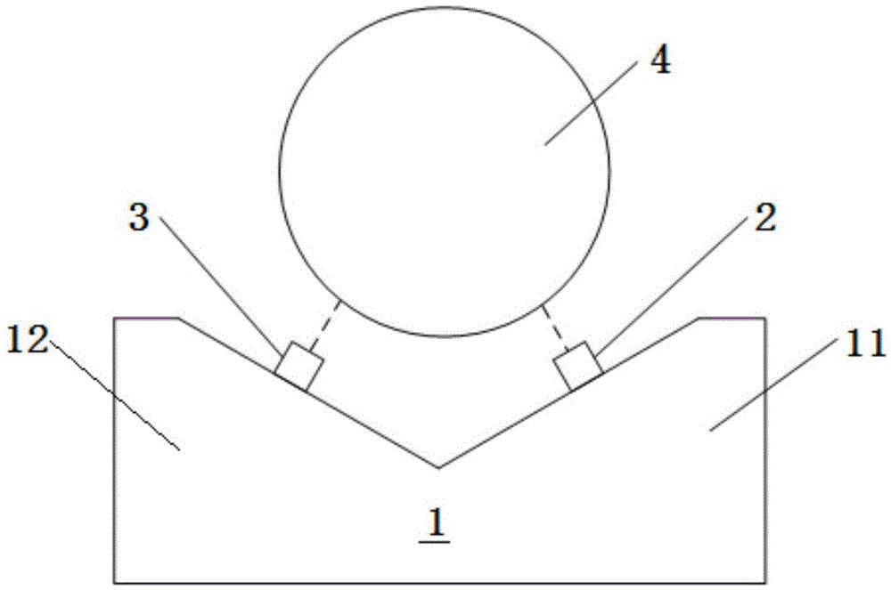
[0052] Such as figure 1 , figure 2 As shown, the journal shaft center measurement device based on the laser displacement sensor of the present invention includes a measurement device for being arranged on the side of the journal 4 of the fixed shaft part for measuring the journal 4 of the shaft part. Frame 1, the measuring frame 1 is composed of a horizontal support 11 with a horizontal plane and a vertical support 12 with a non-horizontal plane, and the horizontal plane of the horizontal support 11 is connected with the non-horizontal support 12 of the vertical support 12. The plane forms an included angle greater than 0 degrees and less than 180 degrees, such as figure 1 Shown is the structural schematic view when the angle formed b...


PUM


Abstract

The invention relates to a laser-displacement-sensor-based journal axle center measurement apparatus, and measurement and calibration methods thereof. The measurement apparatus comprises a measurement rack and two laser displacement sensors; and the two laser displacement sensors are installed on two intersected planes of the measurement rack respectively. The measurement rack is arranged nearby a journal of an axis component, so that a plane formed by intersection of two laser radiation lines is perpendicular to the axial central line of the journal. On the basis of the structure, the laser radiation lines of the two laser displacement sensors are fixed relative to the angel of the measurement rack; coordinates, relative to the measurement rack, of two light spot points of the laser radiation lines on the journal surface are obtained according to measurement values of the laser displacement sensors; on the premise that the diameter of the journal is known and the circular degree deviation can be ignored, position information of the axle center of the journal relative to the measurement rack is calculated based on the coordinates of the two light spot points; and a coordinate system is calculated by using a pin gauge. Therefore, problems existing in the existing image, contact type measurement head and pneumatic gauging methods can be solved; and industrial on-line measurement and application are realized conveniently.

Description

technical field [0001] The invention relates to a shaft center measuring device for shaft journals of shaft parts. In particular, it relates to a measuring device and a measuring and calibrating method for the shaft center of a journal based on a laser displacement sensor. Background technique [0002] Shaft parts are typical parts in the machinery industry. They are mainly used to support transmission parts, transmit torque and bear loads. The mutual position accuracy and geometric shape error of each part of the shaft journal will directly determine the coordination and rotation accuracy of the transmission parts, resulting in friction, vibration and noise, etc., affecting the life of the shaft parts and system energy consumption. [0003] In the measurement of the journal and geometric shape error of shaft parts, it can be quickly detected by instruments and equipment such as vernier calipers, go-no-go gauges, and pneumatic measuring instruments, and the technology is ma...

Claims


Application Information

Patent Timeline
Patent Type & Authority Applications(China)
IPC IPC(8): G01B11/24
Inventor 王仲王磊付鲁华刘尧夫吴振刚李兴强吴翔宇
Owner TIANJIN UNIV
Learn More