Eureka AIR delivers breakthrough ideas for toughest innovation challenges, trusted by R&D personnel around the world.

System and method for measuring evolution rate of radon

A technology of radon exhalation rate and measurement method, which is applied in the field of radon exhalation rate measurement system, can solve the problems of inability to measure measurement results, failure to solve the effects of leakage and back diffusion, and low measurement results, etc.

Inactive Publication Date: 2016-03-23
NANHUA UNIV
View PDF5 Cites 24 Cited by
  • Summary
  • Abstract
  • Description
  • Claims
  • Application Information

AI Technical Summary

Problems solved by technology

[0005] The measurement of radon exhalation rate is greatly affected by meteorological factors such as air pressure, temperature, and humidity. The measurement time of the activated carbon box method is 3-7 days, which is difficult to meet the influence of the changing environmental meteorological factors on the site. When an instrument such as RAD7 measures the radon exhalation rate, a desiccant is used to eliminate the influence of temperature and humidity on the radon concentration measurement, but the use of a desiccant changes the exudation of radon on the surface of the medium to be measured; in addition, the measured average radon concentration needs to be corrected to obtain the instantaneous radon concentration. Concentration, it is necessary to use the computer to correct the instantaneous radon concentration to calculate the measured radon exhalation rate, and the measurement result of the radon exhalation rate cannot be obtained directly after the measurement
Only a small number of radon emission rate measuring instruments can directly give measurement results, such as the ERS-2-s radon thoron analyzer produced by Tracerlab in Germany. This measuring instrument can directly obtain results after the measurement is completed, but the measurement results are always Low, does not address leakage and counterproliferation effects

Method used


Image

  • System and method for measuring evolution rate of radon
  • System and method for measuring evolution rate of radon
  • System and method for measuring evolution rate of radon

Examples


Embodiment 1

[0048] The principle of radon extraction rate measurement:

[0049] 1. Measuring method of radon extraction rate

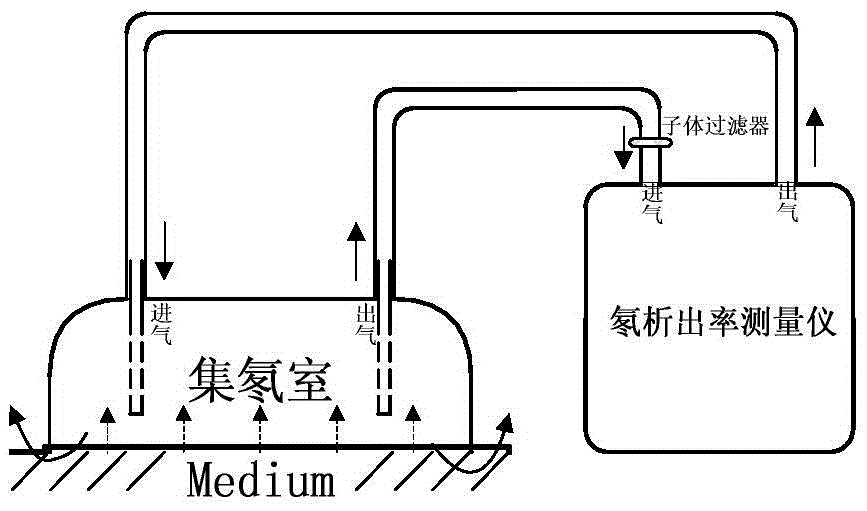
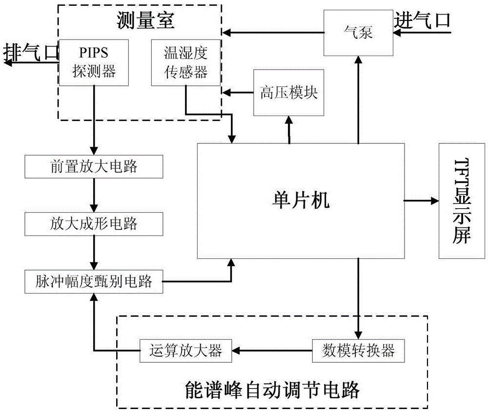
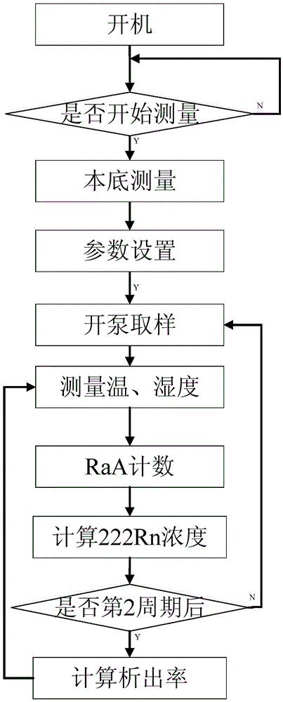
[0050] Automatic measurement of radon extraction rate Such as figure 1 As shown, start the sampling pump and use the QL / min flow rate to extract the radon-containing air ΔT (not less than 1 minute) in the measured environment. At this time, the radon concentration in the measuring room is the radon concentration in the radon room at the initial time t=0. C 0 , Then buckle a radon cover with a volume of (V-ΔV--ΔV1) and a bottom area of ​​S on the surface of the measured medium with a radon extraction rate of J, and then pass a closed measuring chamber with a volume of ΔV through the two tubes The internal volume is ΔV1. The silicone tube is connected with the radon cover to form a loop. After collecting for a certain period of time T-ΔT, turn on the sampling pump to mix the radon chamber with the radon in the measuring chamber at a flow rate of QL / min for ΔT time. Th...


PUM


Abstract

The invention discloses a system and method for measuring the evolution rate of radon. The system does not need a drying tube to dry sample gas, thereby reducing the impact on the evolution rate of radon of the internal dielectric surface of a radon collection cover from a drying agent. In a natural environment, a measurement instrument can accurately measure the instantaneous concentration of radon, and does not need to correct the measured concentration of radon for calculation. The measurement instrument can automatically solve the evolution rate of radon through the measured concentration of radon, and can obtain the value of the evolution rate of radon with no need of a PC for linear fitting processing. An experiment indicates that the measurement error of the radon evolution rate measurement instrument is within the range 5% on a radon evolution rate standard device. After measurement, the evolution rate of radon is directly obtained, thereby meeting the demands of on-site measurement of the evolution rate of radon. The system and method are easy to implement, and are high in measurement efficiency.

Description

technical field [0001] The invention relates to a measurement system and method for radon exhalation rate. Background technique [0002] In 2009, the latest epidemiological study on radon and lung cancer risk published by WHO confirmed that indoor radon can increase the risk of lung cancer in the general population, and adopted stricter control standards for indoor radon. Radon is a preventable and controllable environmental factor, and the measurement of radon exhalation rate is the key to find the source item in environmental radon pollution control. The International Commission on Radiological Protection (ICRP) approved the publication No. 126 "Radiation Protection from Radon Exposure" (ICRP, 2014) in April 2014, pointing out that the committee strongly recommends that the national regulatory authorities should establish a national radon concentration derived reference level. This level should be based on comprehensive consideration of the current economic and social con...

Claims


Application Information

Patent Timeline
IPC IPC(8): G01T1/167G01T1/24
CPCG01T1/167G01T1/24
Inventor 肖德涛李志强赵桂芝
Owner NANHUA UNIV
Why Eureka
Eureka Blog
Learn More