
Collaborative Optimization Method for Light Source Mask

A collaborative optimization and mask technology, applied in optics, originals for opto-mechanical processing, instruments, etc., can solve the problem that layout optimization methods have not received enough attention, and reduce the number of defects, manufacturing costs, and graphics. effect of quantity

Active Publication Date: 2020-02-21
INST OF MICROELECTRONICS CHINESE ACAD OF SCI
View PDF5 Cites 0 Cited by
  • Summary
  • Abstract
  • Description
  • Claims
  • Application Information

AI Technical Summary

Problems solved by technology

Therefore, the layout optimization method in collaborative optimization has not received enough attention

Method used


Image

  • Collaborative Optimization Method for Light Source Mask
  • Collaborative Optimization Method for Light Source Mask
  • Collaborative Optimization Method for Light Source Mask

Examples


Embodiment Construction

[0035] Embodiments of the present invention are described in detail below, examples of which are shown in the drawings, wherein the same or similar reference numerals designate the same or similar elements or elements having the same or similar functions throughout. The embodiments described below by referring to the figures are exemplary only for explaining the present invention and should not be construed as limiting the present invention.

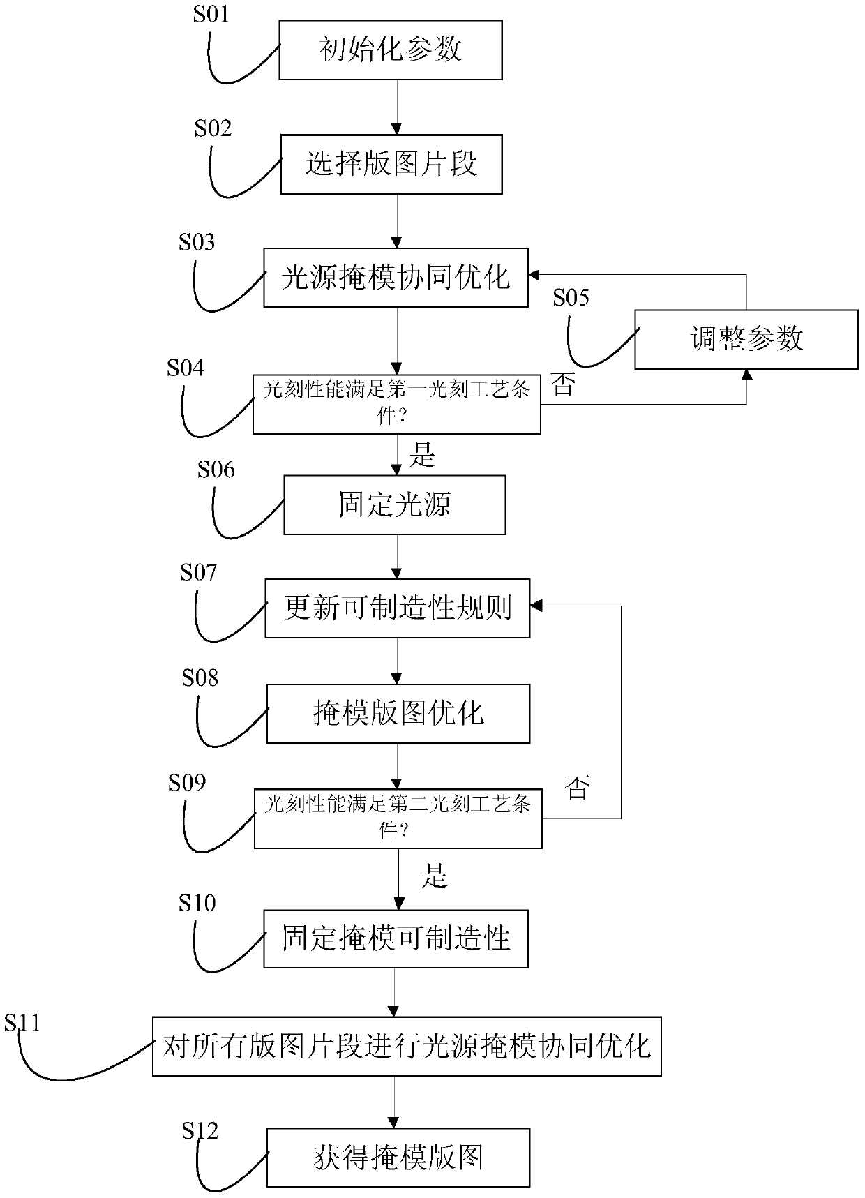
[0036] refer to figure 1 As shown, the present invention proposes a method for collaborative optimization of a light source mask that can simultaneously optimize mask manufacturability, the method comprising:

[0037] In step S01, the initial parameters for optimization are input.

[0038] In the present invention, the optimized initial parameters for lithography include: lithography machine model, light source type, light source polarization state, reticle polarity, numerical aperture, lithography stack information, original mask layou...


PUM


Abstract

The present invention provides a light source mask collaborative optimization method. The method comprises: inputting an initial parameter; selecting part of input layouts for participating in optimization; carrying out light source mask collaborative optimization to obtain an optimized light source meeting photo-etching process conditions; adjusting a mask manufacturability rule and carrying out layout optimization again; according to the case whether the process conditions can be met or not, determining the mask manufacturability rule with the lowest cost; according to the determined manufacturability rule, carrying out layout optimization on all the input layouts; and obtaining the final optimized layouts. According to the method disclosed by the present invention, in the process of light source mask collaborative optimization, mask manufacturability can be subjected to rule optimization, so that the mask manufacturing cost and the defect number after optimization are reduced, the graph number of the layouts participating in the collaborative optimization is also reduced, and optimization efficiency is improved.

Description

technical field [0001] The invention relates to the technical field of semiconductor manufacturing, in particular to a collaborative optimization method for a light source mask in computational lithography. Background technique [0002] Photolithography is one of the most important process steps in the production of integrated circuits. With the development of semiconductor manufacturing technology, the feature size is getting smaller and smaller, and the requirements for resolution in the photolithography process are getting higher and higher. Photolithography resolution refers to the minimum feature size (critical dimension, CD) that can be exposed on the surface of a silicon wafer by a photolithography machine, and is one of the important performance indicators in photolithography technology. At present, the mainstream lithography technology is a deep ultraviolet (Deep Ultraviolet, DUV) immersion optical lithography technology with a wavelength of 193nm, and the limit of...

Claims


Application Information

Patent Timeline
Patent Type & Authority Patents(China)
IPC IPC(8): G03F1/36
Inventor 宋之洋郭沫然韦亚一董立松于丽贤
Owner INST OF MICROELECTRONICS CHINESE ACAD OF SCI
Learn More