Input overvoltage protection circuit used for high-voltage integrated circuit

A high-voltage integrated circuit and overvoltage protection circuit technology, applied in the field of input overvoltage protection circuit, can solve the problems of input voltage overshoot, circuit impact, signal source instability, etc., achieve stable performance, simple circuit structure, and simplify high-voltage integration The effect of the circuit

Inactive Publication Date: 2016-03-23
FORTIOR TECH SHENZHEN
View PDF4 Cites 0 Cited by
  • Summary
  • Abstract
  • Description
  • Claims
  • Application Information

AI Technical Summary

Problems solved by technology

However, in practical applications, due to factors such as unstable signal sources, there will be an overshoot phenomenon when the input voltage reaches the extreme value of the circuit voltage.
In addition, external static electricity will generate extremely high instantaneous voltage at the input end of the circuit, and release instantaneous large current, which will have a great impact on the circuit

Method used


Image

  • Input overvoltage protection circuit used for high-voltage integrated circuit
  • Input overvoltage protection circuit used for high-voltage integrated circuit
  • Input overvoltage protection circuit used for high-voltage integrated circuit

Examples


Embodiment 1

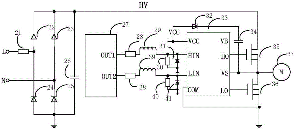
[0027] An embodiment of the present invention provides an input overvoltage protection circuit for a high-voltage integrated circuit, such as figure 1 As shown, the circuit includes a first resistor 1, a second resistor 2, a first Zener diode group 3, and a second Zener diode group 4; wherein one end of the first resistor 1 is connected to the ground of the system, and the other end is connected to The HIN pin of the first high-voltage integrated circuit 5 and the cathode of the first Zener diode group 3, the other end of the first Zener diode 3 is connected to the system ground. One end of the second resistor 2 is connected to the ground of the system, the other end is connected to the LIN pin of the first high voltage integrated circuit 5 and the cathode of the second Zener diode group 3, and the other end of the second Zener diode group 3 is connected to systematically.

Embodiment 2

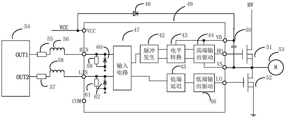
[0029] An embodiment of the present invention provides an input overvoltage protection circuit for a high-voltage integrated circuit, such as figure 2 As shown, the circuit includes a first resistor 1, a second resistor 2, a first Zener diode group 3, and a second Zener diode group 4; wherein, one end of the first resistor 1 is connected to a second high-voltage integrated circuit 6 COM, the other end is connected to the HIN pin of the second high-voltage integrated circuit 6 and the cathode of the first Zener diode group 3, and the other end of the first Zener diode group 3 is connected to the COM of the second high-voltage integrated circuit 6; One end of the second resistor 2 is connected to the COM of the second high-voltage integrated circuit 6, and the other end is connected to the LIN pin of the second high-voltage integrated circuit 6 and the cathode of the second Zener diode group 4, and the second Zener diode group 4 The other end is connected to the COM of the seco...


PUM


Abstract

The invention discloses an input overvoltage protection circuit used for a high-voltage integrated circuit. The input overvoltage protection circuit comprises the components of a first resistor, a second resistor, a first Zener diode set and a second Zener diode set. One end of the first resistor is connected with the anode of the first Zener diode set. The second resistor is connected with the anode of the second Zener diode set. The cathode of the first Zener diode set is connected with the HIN end of the high-voltage integrated circuit. The cathode of the second Zener diode set is connected with the LIN end of the high-voltage integrated circuit. The input overvoltage protection circuit has relatively simple integral circuit structure. Just through appropriately increasing or reducing Zener voltage and number of the Zener diodes, functions of input HIN / LIN overvoltage protection, input HIN / LIN overshoot filtering, input signal source HIN / LIN electrostatic discharge protection, etc. can be realized. Furthermore the input overvoltage protection circuit has stable performance.

Description

technical field [0001] The invention relates to the technical field of high-voltage integrated circuits, in particular to an input overvoltage protection circuit for high-voltage integrated circuits. Background technique [0002] High-voltage integrated circuit (HVIC) is a gate drive circuit with functions such as undervoltage protection and logic control. It combines power electronics with semiconductor technology, gradually replaces traditional discrete components, and is increasingly used in High-power IGBT, MOSFET and other driving fields. [0003] High-voltage integrated circuit application systems are usually composed of high-voltage integrated circuits, power devices, peripheral resistors, capacitors, and inductors. The physical characteristics of MOS tubes in high-voltage integrated circuits determine that they can work normally within an appropriate voltage range. However, in practical applications, due to factors such as unstable signal sources, there will be an ...

Claims


Application Information

Patent Timeline
Patent Type & Authority Applications(China)
IPC IPC(8): H02H9/04
CPCH02H9/046
Inventor 谢正开叶东程春云梁盛林张波毕磊毕超
Owner FORTIOR TECH SHENZHEN
Why Eureka
Try Eureka