Apparatus and method for micro-droplet split in microchannel

A micro-channel and micro-droplet technology, applied in chemical instruments and methods, laboratory containers, laboratory utensils, etc., can solve the fragmentation of lithium niobate substrates, the application difficulty of piezoelectric microfluidic systems, focusing fork Refers to the complex design of the transducer, etc., to achieve the effect of simple design

Inactive Publication Date: 2016-03-30
CHANGZHOU INST OF TECH
View PDF8 Cites 10 Cited by
  • Summary
  • Abstract
  • Description
  • Claims
  • Application Information

AI Technical Summary

Problems solved by technology

Since the micro-reactor requires high electrical signal power to break the micro-droplets located on the PZT piezoelectric substrate, it is easy to break the lithium niobate substrate commonly used in piezoelectric microfluidic systems, and the focused interdigital transduction The device design is more complex, which brings difficulties to the application of piezoelectric microfluidic systems, and needs to be improved

Method used


Image

  • Apparatus and method for micro-droplet split in microchannel
  • Apparatus and method for micro-droplet split in microchannel

Examples


Embodiment 1

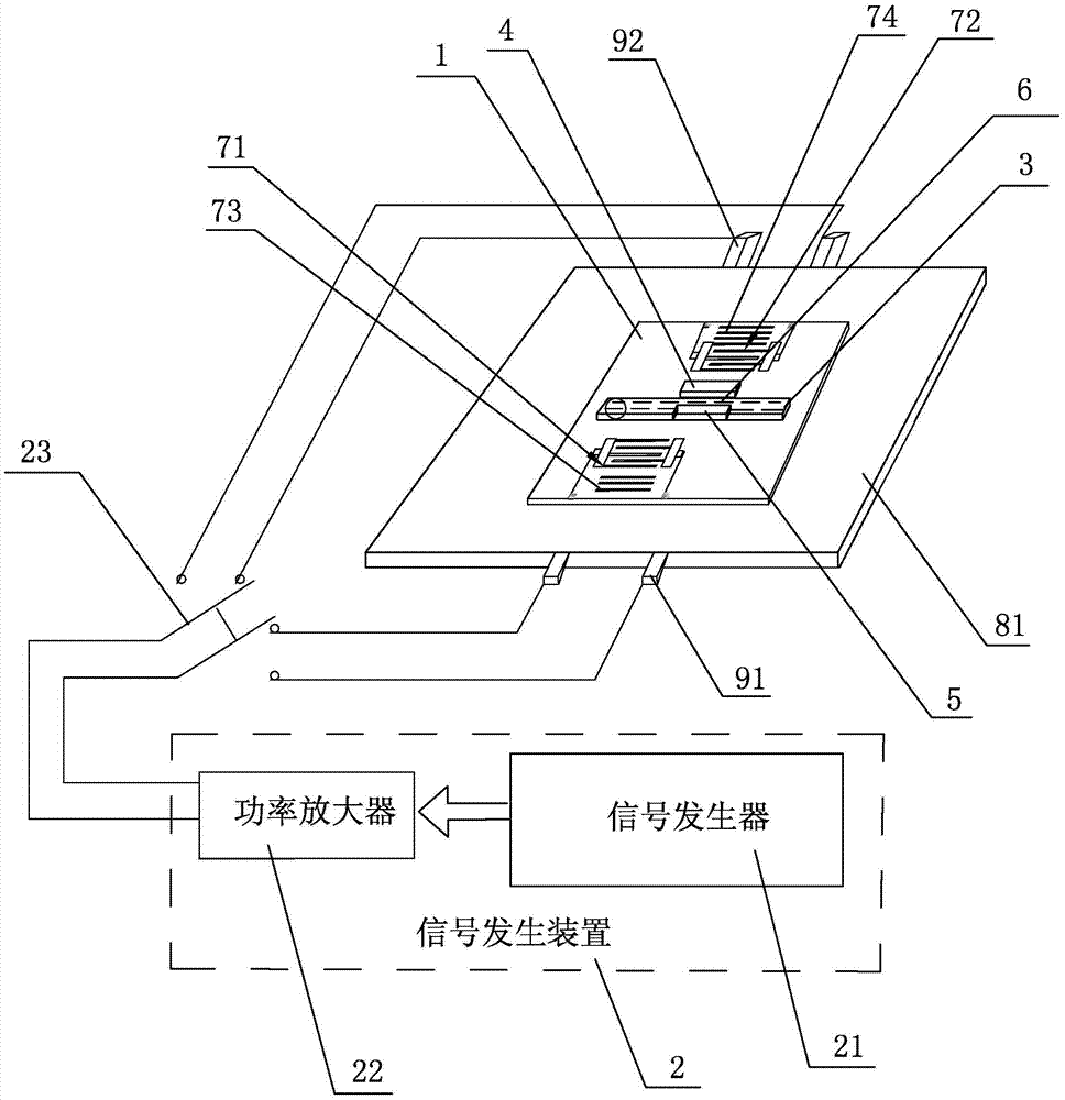
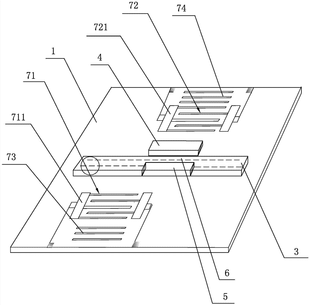
[0038] A device for splitting micro-droplets in a microchannel provided in this embodiment, such as figure 1 and figure 2 As shown, it includes a piezoelectric substrate 1 and a signal generating device 2 for generating RF electrical signals. The upper surface of the piezoelectric substrate 1 is a working surface, and the working surface of the piezoelectric substrate 1 is provided with The microchannel 3 of the droplet, the sound-absorbing coating 4 near the second side of the microchannel 3, two unweighted interdigital transducers respectively connected to the signal generating device 2 and used to excite surface acoustic waves, the microchannel 3 A choke strip 5 with a width less than the width of the lumen of the microchannel 3 and a height consistent with the height of the lumen of the microchannel 3 is arranged inside, and the first side of the choke strip 5 is in contact with the first side of the lumen of the microchannel 3. Wall is close to, because the height of ch...

Embodiment 2

[0048] This embodiment proposes a method corresponding to the device for splitting micro-droplets in the micro-channel of Embodiment 1, which includes the following steps:

[0049] ① Connect the signal generator to the power amplifier, connect the power amplifier to the switch, connect the bus bar of the first unweighted IDT to the first lead pin, and connect the bus bar of the second unweighted IDT with the second pin;

[0050] ② Place the micro-droplets to be split in the front part of the micro-channel;

[0051] ③ Connect the switch to the power amplifier and the first pin, start the signal generator and the power amplifier, the signal generator outputs RF electrical signals, and transmits the RF electrical signals to the power amplifier, and the amplified RF electrical signals output by the power amplifier are transmitted to the second One unweighted interdigital transducer, the first unweighted interdigital transducer excites the surface acoustic wave after receiving the...


PUM


Abstract

The present invention discloses an apparatus and a method for micro-droplet split in a microchannel. The apparatus comprises a piezoelectric substrate and a signal generating apparatus. A microchannel, a sound-absorbing coating and two unweighted inter-digital transducers are arranged on the working surface of the piezoelectric substrate; a flow blocking strip is arranged in the microchannel; the first side surface of the flow blocking strip is tightly adhered to the first side wall of an inner cavity of the microchannel; a sub-channel is formed between the second side surface of the flow blocking strip and the second side wall of the inner cavity of the microchannel; surface acoustic waves excited by the first unweighted inter-digital transducer are applied to micro-droplets transported in the front portion of the microchannel, and the micro-droplets move towards an inlet of the sub-channel under the effect of a continuous oil phase microfluid; most of surface acoustic waves excited by the second unweighted inter-digital transducer are absorbed by the sound-absorbing coating, and a small portion of the surface acoustic waves are applied to a part of the micro-droplets exposed outside of the outlet of the sub-channel to achieve split. The apparatus and the method have the advantages that the micro-droplet split can be achieved with relatively low electrical signal power, so that the piezoelectric substrate is effectively avoided from being broken.

Description

technical field [0001] The invention relates to a micro-droplet splitting technology in a micro-channel in a microfluidic chip, in particular to a device and method for splitting a micro-droplet in a micro-channel. Background technique [0002] Microfluidic technology can integrate a series of sampling, sample pretreatment, separation, reaction, detection and data analysis on a microfluidic substrate, which greatly reduces the cost of microfluidic analysis and shortens the time of microfluidic analysis. Therefore, Microfluidic chips with microfluidic technology as the core have been widely used in biochemical analysis fields such as DNA sequencing, protein analysis, single cell analysis, drug detection and food safety. In the microfluidic analysis system, the working forms of microfluidics are divided into two categories, namely, the continuous flow form and the digital flow form. The consumption of samples or reagents is small, the analysis time is short, and the analysis ...

Claims


Application Information

Patent Timeline
Patent Type & Authority Applications(China)
IPC IPC(8): B01L3/00
CPCB01L3/5027B01L3/50273B01L2300/06B01L2300/0809B01L2300/161
Inventor 章安良张小权胡文艳陈森陆雨枫张晴雯
Owner CHANGZHOU INST OF TECH
Why Eureka
Try Eureka