Fully-automatic narrow lap electric-resistance seam-welding machine for thin plates

A resistance seam welding, fully automatic technology, applied in the direction of resistance welding equipment, resistance electrode holder, welding/welding/cutting items, etc., can solve the problem of high cost of sliding conductive bearing, high cost of wheel welding machine head, and the use of copper materials Large volume and other problems, to achieve the effect of shortening the time of relative movement, improving shearing efficiency, and improving processing efficiency

Active Publication Date: 2016-03-30
CHENGDU HANYAN TECH
View PDF8 Cites 13 Cited by
  • Summary
  • Abstract
  • Description
  • Claims
  • Application Information

AI Technical Summary

Problems solved by technology

The conduction method of the traditional wheel welding machine is to introduce the current into the support seat of the welding wheel, and then transmit the current to the welding wheel through the sliding conductive bearing and the rotating shaft. There are too many intermediate links, and because the parts that conduct large current must be made of copper, the wheel The parts on the welding machine head are all made of copper, and the copper is used in a large amount, so the cost of the wheel welding machine head is too high; at the same time, the cost of the sliding conductive bearing is also high and it is not easy to replace

Method used


Image

  • Fully-automatic narrow lap electric-resistance seam-welding machine for thin plates
  • Fully-automatic narrow lap electric-resistance seam-welding machine for thin plates
  • Fully-automatic narrow lap electric-resistance seam-welding machine for thin plates

Examples


Embodiment 1

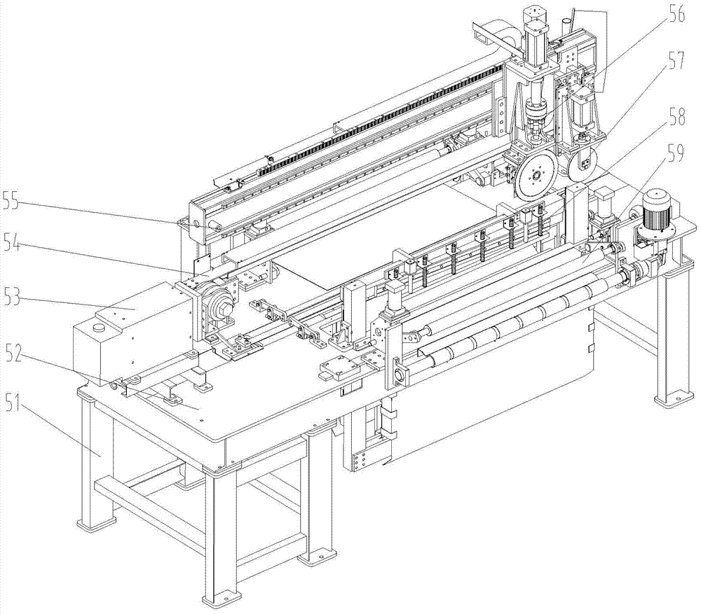
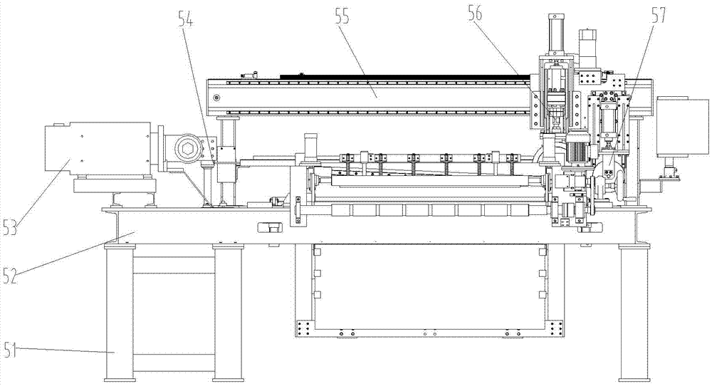
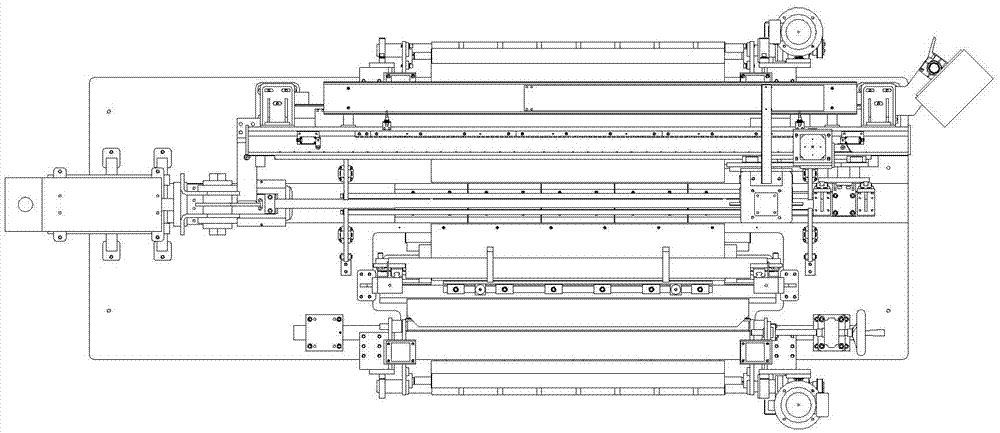
[0060]A fully automatic narrow lap resistance seam welding machine for thin plates, comprising a frame 51 and a workbench 52 located on the frame 51, the feed side of the frame 51 or the workbench 52 is sequentially provided with pinch feeding along the feed direction Device 59, single-edged scissors 58, described frame 51 is connected with beam assembly 55, and described beam assembly 55 is connected with resistance welding device 56 and rolling device 57 that can move along the length direction of beam assembly 55; The blade scissors 58 include a frame 35 installed on the workbench 52, between the left frame 351 of the frame 35 and the right frame 352 of the frame 35, an upper clip 36 and a lower clip 39 are arranged, wherein the upper clip 36 is fixedly connected 1. The lower cutting piece 39 is movably connected, and the lower cutting piece 39 is located between the upper cutting piece 36 and the bottom frame 353 of the frame 35, and the bottom frame 353 of the frame 35 is ...

Embodiment 2

[0062] A fully automatic narrow lap resistance seam welding machine for thin plates, comprising a frame 51 and a workbench 52 located on the frame 51, the feed side of the frame 51 or the workbench 52 is sequentially provided with pinch feeding along the feed direction Device 59, single-edged scissors 58, described frame 51 is connected with beam assembly 55, and described beam assembly 55 is connected with resistance welding device 56 and rolling device 57 that can move along the length direction of beam assembly 55; The blade scissors 58 include a frame 35 installed on the workbench 52, between the left frame 351 of the frame 35 and the right frame 352 of the frame 35, an upper clip 36 and a lower clip 39 are arranged, wherein the upper clip 36 is flexibly connected , the lower cutting piece 39 is fixedly connected, and the lower cutting piece 39 is located between the upper cutting piece 36 and the bottom frame 353 of the frame 35, and the bottom frame 353 of the frame 35 is...

Embodiment 3

[0064] A fully automatic narrow lap resistance seam welding machine for thin plates, comprising a frame 51 and a workbench 52 located on the frame 51, the feed side of the frame 51 or the workbench 52 is sequentially provided with pinch feeding along the feed direction Device 59, single-edged scissors 58, described frame 51 is connected with beam assembly 55, and described beam assembly 55 is connected with resistance welding device 56 and rolling device 57 that can move along the length direction of beam assembly 55; The blade scissors 58 include the frame 35 installed on the workbench 52, between the left frame 351 of the frame 35 and the right frame 352 of the frame 35, an upper cutting sheet 36 and a lower cutting sheet 39 are arranged, and the lower cutting sheet 39 is located at Between the upper cutting piece 36 and the bottom frame 353 of the frame 35, the bottom frame 353 of the frame 35 is connected with a shear cylinder 37, and the end of the output shaft of the shea...


PUM


Abstract

The invention discloses a fully-automatic narrow lap electric-resistance seam-welding machine for thin plates, belongs to a thin plate seam-welding machine in the welding technical field, and aims to provide the fully-automatic narrow lap electric-resistance seam-welding machine, which is high in shearing efficiency and long in service life, for thin plates. According to the technical scheme, the fully-automatic narrow lap electric-resistance seam-welding machine comprises a rack and a workbench, wherein a clamping and delivering device and a single-blade shear are arranged on the rack or the workbench; a beam assembly is connected on the rack; a resistance welding device and a grinding device are connected on the beam assembly; the single-blade shear comprises a framework, wherein an upper shearing sheet, a lower shearing sheet and a shearing air cylinder are connected on the framework; a synchronous slide block is connected on the shearing air cylinder; link mechanisms are connected on the synchronous slide block; the two groups of link mechanisms are symmetrically arranged at left and right sides of the synchronous slide block, the upper shearing sheet and the lower shearing sheet; and the other ends of the link mechanisms are connected to the upper shearing sheet or the lower shearing sheet. The fully-automatic narrow lap electric-resistance seam-welding machine is suitable for shearing and welding metal thin plates in a finish machining continuous line of the metal thin plates.

Description

technical field [0001] The invention belongs to the field of welding technology and relates to a thin plate seam welding machine. Background technique [0002] Seam welding machine refers to the resistance welding machine in which the weldment is assembled into a lap or butt joint and placed between two roller electrodes. The roller electrode pressurizes the weldment and rotates, and continuously or intermittently pulses power to form a continuous weld. . It can also be said that the seam welder is an evolution of spot welding. Seam welding is widely used in the manufacture of joints that require airtightness, and sometimes it is also used to weld ordinary non-airtight sheet metal parts. The thickness of the metal material to be welded is usually 0.1-2.5mm. [0003] In the steel strip finishing continuous line using coiled steel plate or steel strip as raw material, the length of the entire production line can be from 50 meters to several kilometers long, and there are man...

Claims


Application Information

Patent Timeline
Patent Type & Authority Applications(China)
IPC IPC(8): B23K11/06B23P23/04B23D15/12B23D15/06B21D1/02B23K11/31B23K11/36B23K101/18
CPCB21D1/02B23D15/06B23D15/12B23K11/06B23K11/31B23K11/36B23K2101/18B23P23/04
Inventor 傅雄飞杨仕海
Owner CHENGDU HANYAN TECH
Why Eureka
Try Eureka