Wind-driven vehicle/vessel and upwind and crosswind running method thereof

A technology of vehicles and sails, which is applied in the field of wind-driven vehicles and their headwind and cross-wind driving, which can solve the problems of blank, wind-driven vehicles and ships unable to realize head-wind and cross-wind driving, and achieve the effect of environmental protection and saving fossil energy

Inactive Publication Date: 2016-03-30
罗琮贵
View PDF8 Cites 0 Cited by
  • Summary
  • Abstract
  • Description
  • Claims
  • Application Information

AI Technical Summary

Problems solved by technology

However, at present, cars or boats directly driven by wind only use low-altitude wind, and there is still a blank for the technology of directly driving vehicles and boats with strong high-altitude wind.
[0003] Moreover, so far, wind-driven vehicles and boats are still unable to achieve headwind and crosswind travel.

Method used


Image

  • Wind-driven vehicle/vessel and upwind and crosswind running method thereof
  • Wind-driven vehicle/vessel and upwind and crosswind running method thereof
  • Wind-driven vehicle/vessel and upwind and crosswind running method thereof

Examples


Embodiment 1

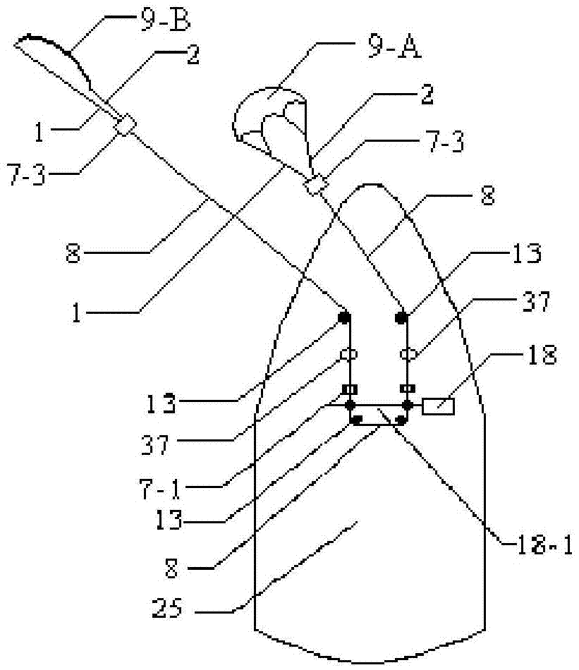
[0063] Embodiment one: if figure 1 On the deck of the ship, the kite generator described in embodiment one or embodiment two is provided with a kite type or a floating bag type kite generator (preferably a floating bag type), and the guide pulley 13 is also connected with the deck, and the kite body 9 Be connected with lightweight air bag 9-10, and the electric motor of ship or storage battery are made circuit connection with generator. Two cable retracting machines 37 are connected on the cable C8, and the supports of these two cable retracting machines are equipped with wheels, and the wheels are connected with the deck or the track on the deck (the purpose is to make the two cable retracting machines expand and contract with the cable C8). for linear reciprocating motion). In actual use, the two cable retractors must reclaim or lengthen the cable C8 at the same time. The purpose is to make the two kites 9 rise to the upper wind at the same time or fall to the lower wind at...

Embodiment 2

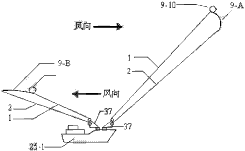
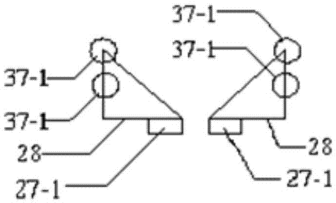
[0064] Embodiment two: if figure 2 , image 3 , the two zither bodies are respectively in the upper and lower wind layers and are opposite to each other, the cable retractor 37 is connected with the outer ring (or inner ring) of the bearing 27-1, and the inner ring (or outer ring) of the bearing 27-1 is connected with the ship The deck is connected, and the connection point should be at the front of the ship, which ensures that when another kite is towed (that is, when the direction of towing is changed), the U-turn problem of the kite body is guaranteed. In actual use, when pulling the hull forward, one kite must be in a fully charged state and the other kite must be in a fully discharged state; when the ship needs to park, the two kites should be in a fully charged state or simultaneously fully de-energized state.


PUM


Abstract

A wind-driven vehicle / vessel is provided with one or two buoyancy lift mechanisms connected to the vehicle / vessel through mooring ropes; if one buoyancy lift mechanism is arranged, the wind-driven vehicle / vessel needs to be capable of being independently lifted through the buoyancy without natural wind; if two buoyancy lift mechanisms are arranged, the two buoyancy lift mechanisms are operated at an upper wind layer and a lower wind layer different from the upper wind layer in height and opposite to the upper wind layer in wind direction respectively, need to be capable of changing the proportion of windward areas of the two buoyancy lift mechanisms or are connected to the vehicle / vessel through respective mooring ropes or are connected to the vehicle / vessel through one mooring rope after being connected into a whole through the mooring ropes or connection rods or supports. Because seven groups of converse wind in the vertical direction exist on the Earth, by controlling one buoyancy lift mechanism to enter wind layers of different wind directions or controlling the windward areas and the windward angles of the two buoyancy lift mechanisms, the wind-driven vehicle / vessel can be run downwind, upwind or across wind, and the vessel can be braked in time during navigation and can be berthed without dropping anchors.

Description

technical field [0001] The invention relates to a wind-driven vehicle and ship and a method for running against the wind and across the wind, and relates to a vehicle and ship powered by wind power and a method for driving the vehicle and ship by wind power. Background technique [0002] High-altitude wind is far stronger than low-altitude wind, and high-altitude wind has the characteristics of stable wind direction and long-lasting wind force. Therefore, high-altitude wind should be a more reliable and economical choice for wind-driven vehicles and ships. Yet the car or boat that is directly driven by wind all only utilizes low-altitude wind power at present, is still blank for the technology that utilizes strong high-altitude wind power to directly drive vehicles and boats. [0003] And, so far, wind-driven vehicles and boats still can't realize traveling against the wind and traveling across the wind. This technical problem cannot be overcome, and it is also one of the m...

Claims


Application Information

Patent Timeline
IPC IPC(8): B60K16/00B63H9/00
CPCB60K16/00B60K2016/006B63H9/00F03B13/00F03B17/06F03D5/00F03D5/06F03D9/00F05B2240/9172Y02E10/30Y02E10/70Y02E10/72Y02E10/728Y02T10/90
Inventor 罗琮贵
Owner 罗琮贵
Why Eureka
Try Eureka