
Compound type connection shear wall structure and assembling method thereof

A shear wall and composite technology, applied in the direction of walls, building components, building structures, etc., can solve the adverse effects of building appearance and waterproof performance, the impact of shear walls on structural safety, and the difficulty of precise docking between upper and lower walls, etc. problems, to achieve the effect of shortening the assembly cycle, reducing assembly workload, and improving construction accuracy

Active Publication Date: 2016-03-30
ZHEJIANG UNIV +2
View PDF8 Cites 44 Cited by
  • Summary
  • Abstract
  • Description
  • Claims
  • Application Information

AI Technical Summary

Problems solved by technology

However, it is often difficult to achieve precise docking between the upper and lower walls connected by the traditional sleeve grouting construction technology, which can easily cause misalignment between the upper and lower shear walls, which not only adversely affects the appearance and waterproof performance of the building, but also The safety of the structure is affected by the eccentric compression of the shear wall
In addition, the existing relevant regulations stipulate that the floor slab must have a cast-in-place layer, and the upper shear wall can only be assembled with the existing construction technology after the floor concrete reaches a certain strength, which will slow down the construction progress

Method used


Image

  • Compound type connection shear wall structure and assembling method thereof
  • Compound type connection shear wall structure and assembling method thereof
  • Compound type connection shear wall structure and assembling method thereof

Examples


Embodiment Construction

[0031] The present invention will be further described below in conjunction with the accompanying drawings and embodiments.

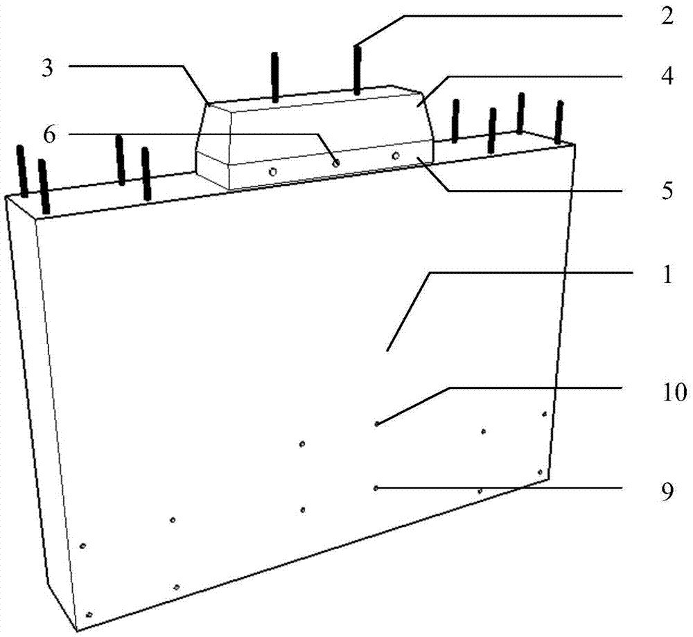
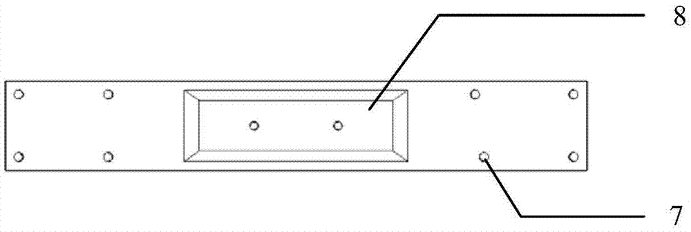
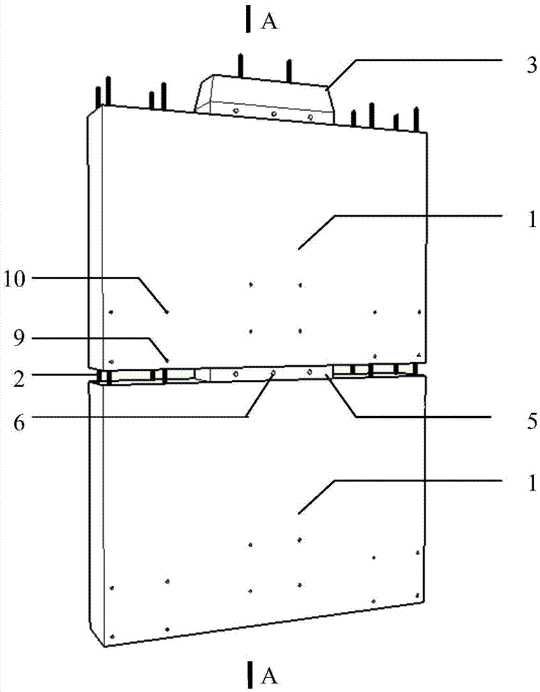
[0032] Such as figure 1 , figure 2 , image 3 As shown, the present invention includes N pieces of shear wall components 1 with the same structure, and every two pieces of shear wall components are connected by composite shear keys 3 and key grooves 8 to form a composite connected shear wall.

[0033] 1-2 rows ( figure 1 , image 3 2 rows in the middle) longitudinal reinforcement 2, and at least one composite shear key 3 is set in the middle of the upper end ( Figure 1~3 The composite shear key is 1), the upper part of the composite shear key is the embedded part 4 of the shear key, and the lower part is the embedded part 5 of the shear key. The thickness of 12 is equal, the width is less than the thickness of the shear wall, and there are a plurality of reserved holes 6 for the reinforcement of the laminated floor 12 on both sides of the shear w...


PUM


Abstract

The invention discloses a compound type connection shear wall structure and an assembling method thereof. The compound type connection shear wall structure comprises N shear wall components of the same structure, wherein every two adjacent shear wall components are connected through a compound shear key and a key groove so that a compound type connection shear wall can be formed. Due to the mutual guide-in effect of the compound shear keys and the key grooves, the construction precision is improved, and eccentric compression generated by inaccurate assembling is avoided. Because the shear key on each shear wall component below can bear the weight of the corresponding shear wall component above when the next layer is assembled, assembling of a wall body of a previous layer can be instantly conducted after floor pouring is completed without waiting till floor concrete reaches the strength, and the assembling cycle of floors can be greatly shortened. The shear keys of the shear wall components below are embedded in the key grooves of the shear wall components above, the shear keys can bear transverse shearing force, the shear resistance of the structure is enhanced, and reliability of the structure is enhanced.

Description

technical field [0001] The invention relates to an assembled shear wall structure and an assembly method thereof, in particular to a compound connected shear wall structure and an assembly method thereof. Background technique [0002] Compared with the traditional cast-in-place concrete structure, the prefabricated concrete structure has many advantages such as good component quality, short construction period, less resource use, and less production waste. Its main feature is that the main structural components are prefabricated in the factory, and then the components are transported to the construction site by means of vehicle transportation, etc., and the components are assembled and connected by means of mechanical hoisting on site. A large number of construction site operations are replaced by centralized production in the factory. [0003] Sleeve grouting technology is one of the common methods for connecting upper and lower shear walls in prefabricated concrete shear w...

Claims


Application Information

Patent Timeline
IPC IPC(8): E04B2/00E04B1/04
CPCE04B1/04E04B1/043E04B2/00
Inventor 张沈斌卓新吴建挺陆其荣周观根
Owner ZHEJIANG UNIV
Learn More