
Static index testing platform and method for industrial robot joint decelerator
A joint reducer, industrial robot technology, applied in the direction of machine gear/transmission mechanism testing, etc., can solve the problems of large fluctuations in test results, manual loading, poor loading accuracy, etc., to improve test efficiency, reduce test errors, The effect of improving test accuracy
- Summary
- Abstract
- Description
- Claims
- Application Information
AI Technical Summary
Problems solved by technology
Method used
Image

Examples
Embodiment Construction
[0027] The present invention will be described in detail below in conjunction with the accompanying drawings.
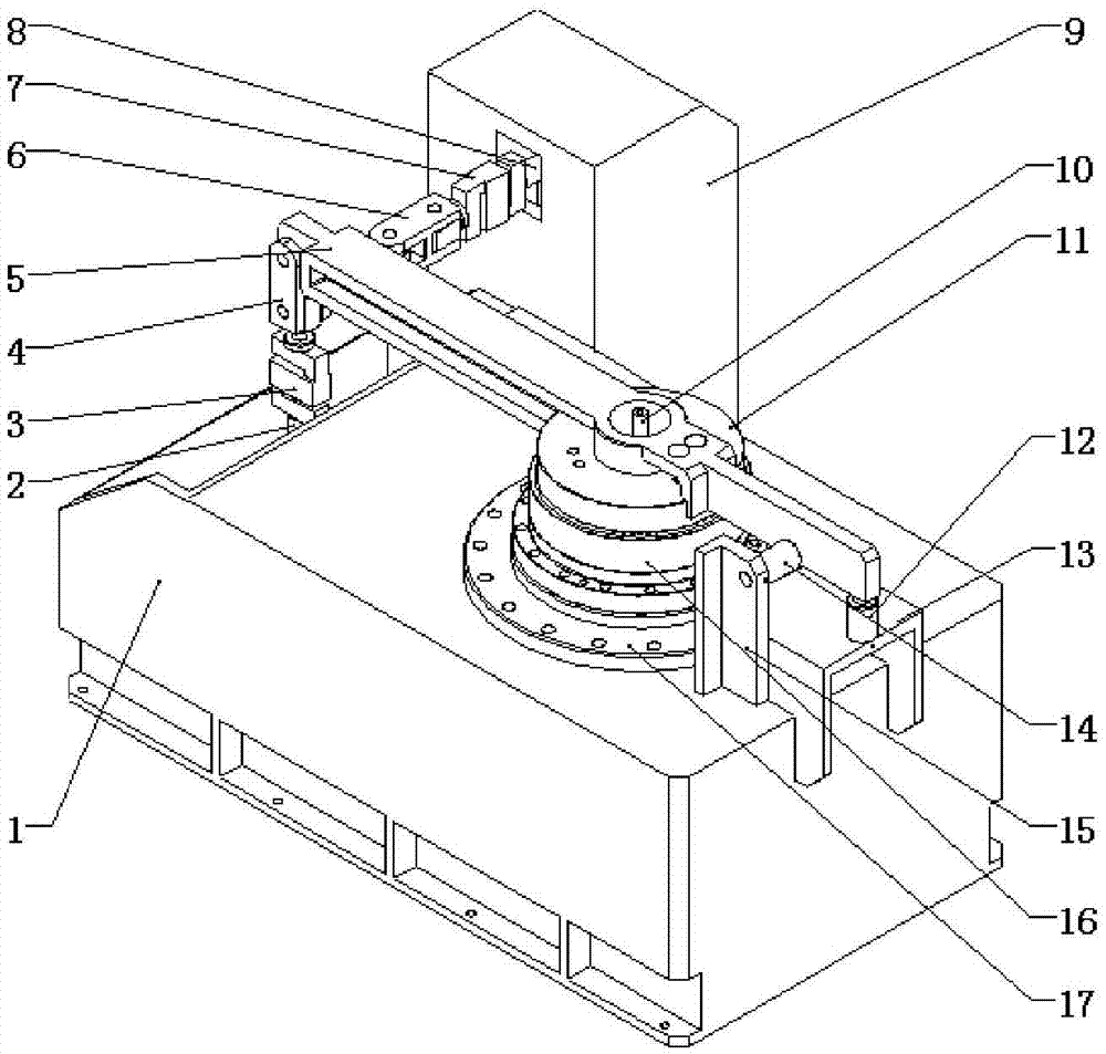
[0028] Such as figure 1 As shown, an industrial robot joint reducer static index test platform of the present invention includes a first tension pressure sensor 3, a first coupling shaft 4, a moment arm 5, a second coupling shaft 6, a second tension pressure sensor 7, and a second tension pressure sensor 7. Automatic loading device 8, reducer pallet 17 and fuselage base 1, the structure of the second automatic loading device 8 and the first automatic loading device 2 is identical; Fuselage base 1 is provided with reducer pallet 17 and the first automatic loading device 2, And the first automatic loading device 2 is fixed on the fuselage base 1 .
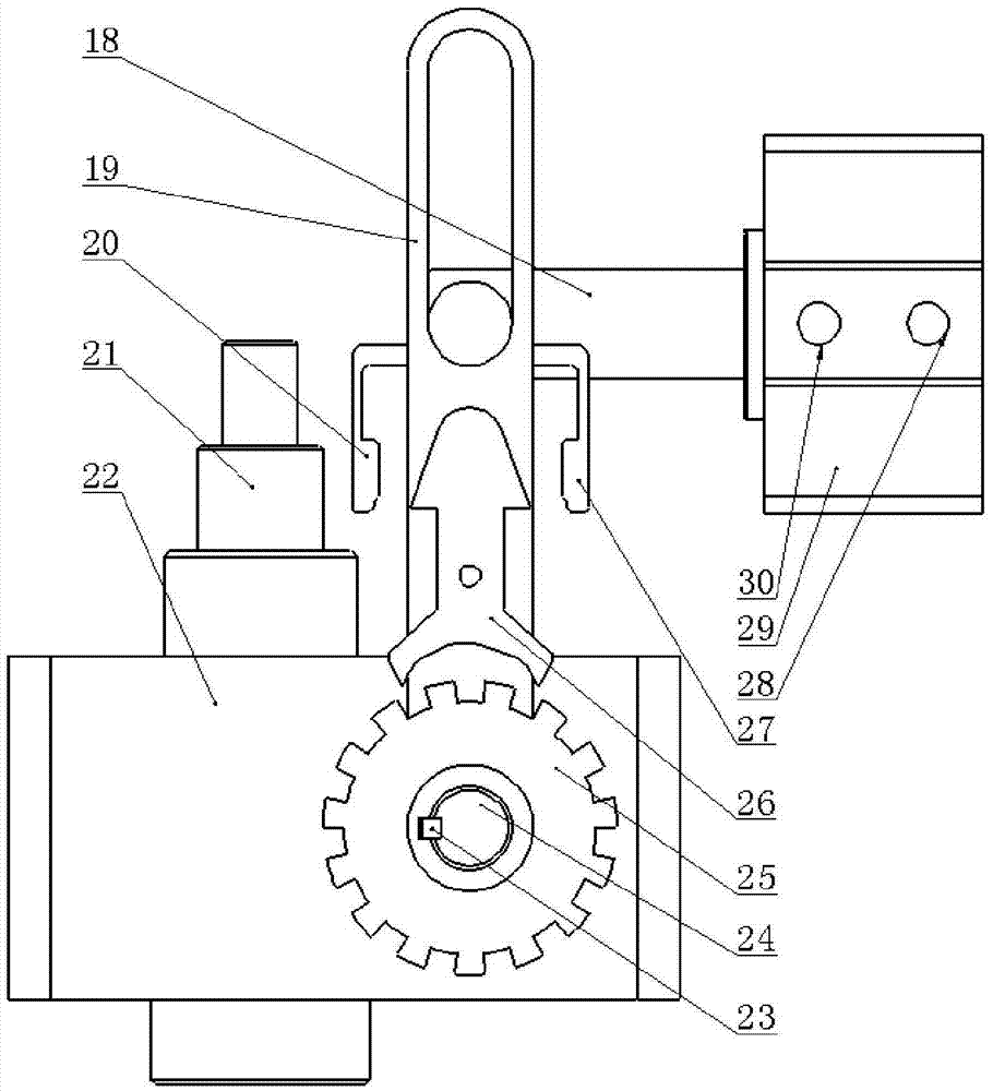
[0029] see figure 2, the first automatic loading device 2 includes a thin cylinder 29 and a screw jack 22, the output screw 21 of the screw jack 22 is used as the execution output end of the automatic loading device, the...
PUM
 Abstract
Description
Claims
Application Information