3D imaging grating assembly and 3D display device

A display device and 3D technology, applied in the field of 3D display, can solve the problems of large volume, large thickness, and difficulty in full lamination, etc., and achieve the effects of simplifying the installation process, simple processing process, and reducing weight

Inactive Publication Date: 2016-03-30
WANWEI CLOUD VISION SHANGHAI DIGITAL TECH CO LTD
View PDF6 Cites 18 Cited by
  • Summary
  • Abstract
  • Description
  • Claims
  • Application Information

AI Technical Summary

Problems solved by technology

[0011] In order to solve the problem that the existing lenticular lens array is bulky and heavy due to its large thickness, which is not conducive to processing and installation, and the existing lenticular lens array is often attached to a rigid or semi-rigid medium, while LCD or LED display panels It is a problem of flexibility or the surface is not completely flat, and it is difficult to fully fit. Embodiments of the present invention provide a 3D imaging grating assembly and a 3D display device

Method used


Image

  • 3D imaging grating assembly and 3D display device
  • 3D imaging grating assembly and 3D display device
  • 3D imaging grating assembly and 3D display device

Examples


Embodiment 1

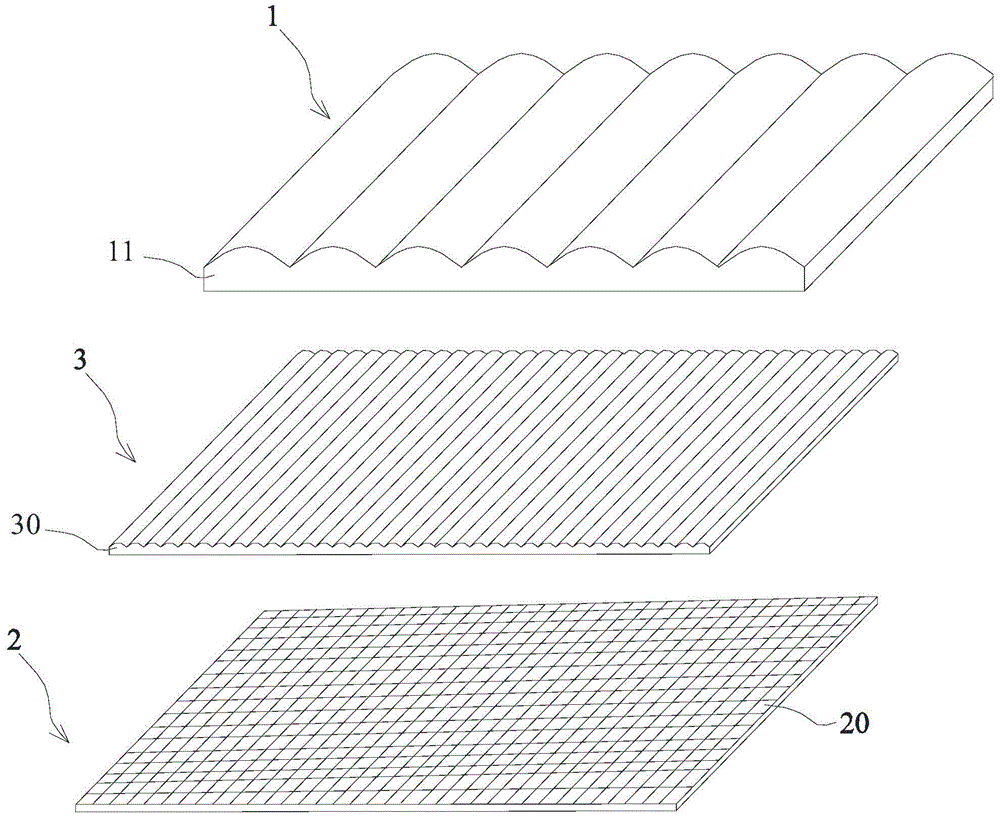
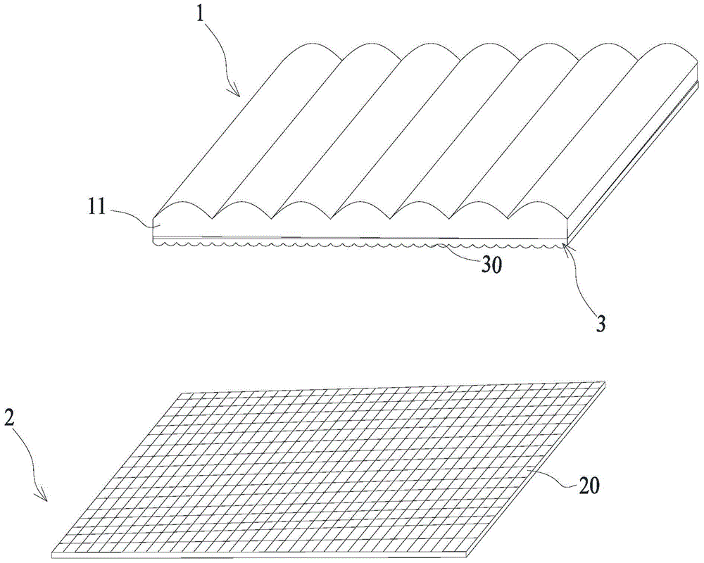
[0040] This example will describe in detail the 3D imaging grating assembly disclosed in the present invention, such as Figure 2a , Figure 2b As shown, it discloses a three-dimensional exploded schematic diagram of a 3D display device including a 3D imaging grating assembly and a display panel 2; the 3D imaging grating assembly includes a spectroscopic lens array grating 1 and a collimating lens array grating 3;

[0041] The collimating lens array grating 3 is provided with several collimating lenses 30 distributed in an array;

[0042] The beam-splitting lens array grating 1 includes several beam-splitting lenses 11 arranged in an array;

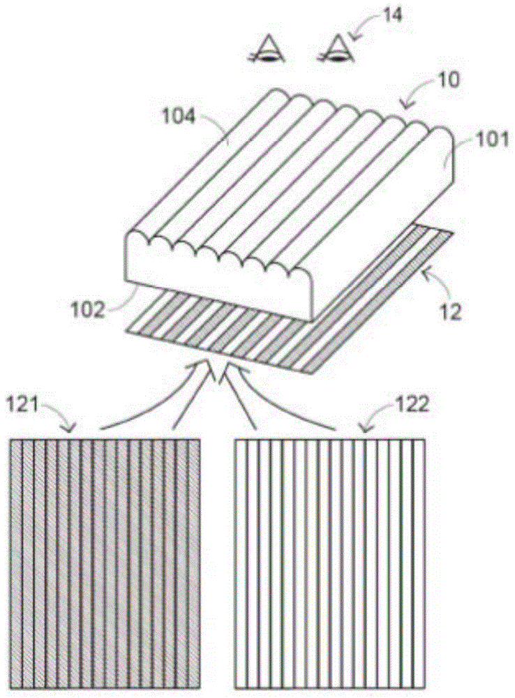
[0043] Among them, such as image 3 As shown, the width D of the collimating lens is 1 / N of the width of a pixel or sub-pixel (the following will be illustrated in units of pixels) of the display panel 2, and the width H of the dichroic lens 11 is 1 / N of the width of the display panel 2. 2 M times the width of the viewpoint group, wher...

Embodiment 2

[0066] In this example, a 3D display device will be described with reference to the accompanying drawings. like image 3 As shown, including a display panel 2 and a 3D imaging grating assembly;

[0067] The 3D imaging grating assembly is installed in front of the display panel 2 .

[0068] When installing, such as Figure 6-Figure 8 As shown, the 3D imaging grating assembly is installed in front of the display panel 2 by using a transparent medium 4 , that is, one side of the collimator lens array grating 3 is pasted on the display panel 2 . Specifically, the thickness of the transparent medium 4 is related to the width of the pixels on the display panel 2 and the divergence angle θ.

[0069] like Image 6 , Figure 7 As shown, each pixel or sub-pixel on the display panel 2 is a light source, such as an LED light 21 . In the figure, w1 is the thickness of the thinnest part of the collimating lens 30 , and w2 is the distance between the collimating lens 30 and the surface...


PUM


Abstract

In order to solve a problem that a conventional light-splitting lens has a great thickness so as to be large in size and heavy in weight and unbeneficial to processing and installation, the embodiment of the invention provides a 3D imaging grating assembly and a 3D display device. The 3D imaging grating assembly comprises a light-splitting lens array grating and a collimating lens array grating. The width of each collimating lens is 1/N of the width of a pixel or sub-pixel of a display panel and the width of each light-splitting lens is M times the width of a viewpoint group on the display panel, wherein the N and the M are natural numbers. The 3D imaging grating assembly may decrease the thickness of the light-splitting lens array grating so as to be lower in thickness and weight. Thus, the 3D imaging grating assembly can be directly installed on the surface of the display panel in a full-clinging way, thereby being simplified in installation process. Further, the 3D imaging grating assembly is easy to process and suitable for batch production.

Description

technical field [0001] The invention relates to the field of 3D display, in particular to a cylindrical lens (LC) 3D display applied in 3D display. Background technique [0002] The current 3D (namely 3Dimension, Chinese: three-dimensional) display technology can be divided into naked-eye type and glasses type. The naked-eye 3D technology can be divided into three types: lens array type, barrier fence type and pointing light source type. The principle and imaging effect of each technology have certain differences. [0003] Among them, the barrier barrier type (full name in English: Parallax Barriers, Chinese is also translated as parallax barrier or parallax barrier), its principle is similar to that of the polarized 3D type, and its principle is to set a grating in front or behind the display panel. The light-transmitting slits and the opaque grating lines between the light-transmitting slits; these light-transmitting slits are tens of microns wide, and the light passing t...

Claims


Application Information

Patent Timeline
Patent Type & Authority Applications(China)
IPC IPC(8): G02B5/18G02B27/22
Inventor 王大力李应樵
Owner WANWEI CLOUD VISION SHANGHAI DIGITAL TECH CO LTD
Why Eureka
Try Eureka