
Connector and contactor assembly

A connector and contactor technology, applied in relays, electrical components, electromagnetic relays, etc., can solve the diversification limitation of contactor or relay control circuit, high contactor cost and product maintenance cost, and increase in contactor or relay cost, etc. problems, to achieve the effect of expanding physical limitations, avoiding electromagnetic interference, and releasing limited space

Inactive Publication Date: 2016-03-30
TYCO ELECTRONICS (SHANGHAI) CO LTD
View PDF5 Cites 4 Cited by
  • Summary
  • Abstract
  • Description
  • Claims
  • Application Information

AI Technical Summary

Problems solved by technology

This method is simple for client applications, but the cost of contactors and product maintenance is relatively high
In addition, when the contactor or relay is combined with multiple control circuits, the wiring and connection of the circuit become complicated, which leads to an increase in the cost of the contactor or relay
At the same time, in the process of miniaturization, simplification, and generalization of contactors or relays, the development of diversification of contactors or relay control circuits is bound to be limited.

Method used


Image

  • Connector and contactor assembly
  • Connector and contactor assembly
  • Connector and contactor assembly

Examples


Embodiment Construction

[0039] Reference will now be made to specific embodiments, examples of which are illustrated in the accompanying drawings. In the detailed description of particular embodiments, directional terms such as "top", "bottom", "above", "below", "left", "right", etc. are used with reference to the directions described in the drawings. Since components of embodiments of the present invention may be arranged in many different orientations, directional terms are used for purposes of illustration and are by no means limiting. Wherever possible, the same or similar numbers and symbols will be used throughout the drawings to refer to the same or like parts.

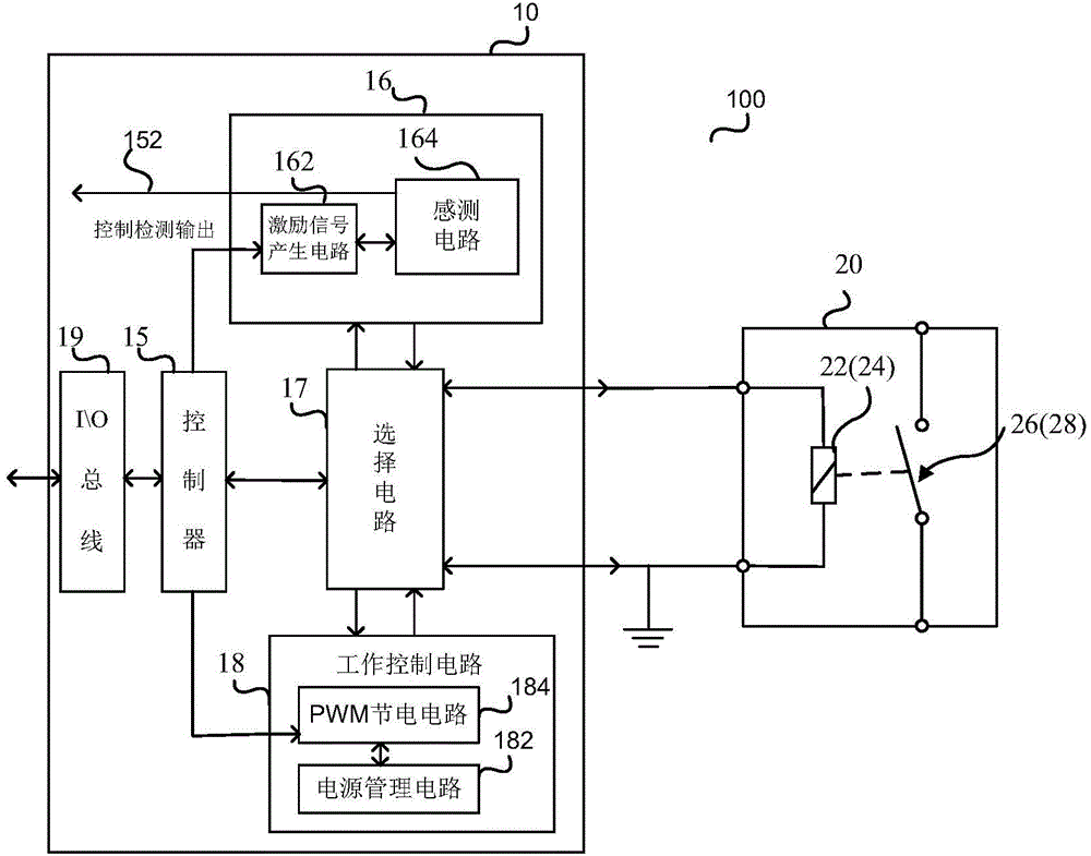
[0040] figure 1 It is a schematic diagram of the circuit structure of the contactor 20 in the first embodiment of the present invention.

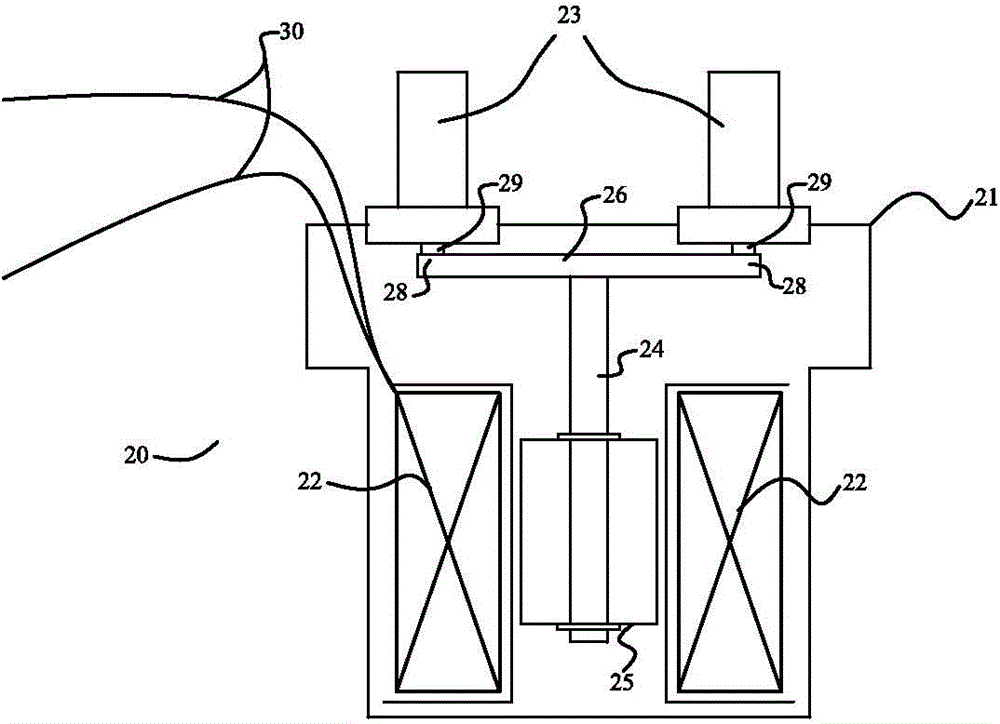
[0041] Such as figure 1 As shown, the contactor (or relay) 20 includes a control circuit 10 connected to the contactor 20 . The contactor 20 has a contactor housing 21 (see Figure 3A-3B ), th...


PUM


Abstract

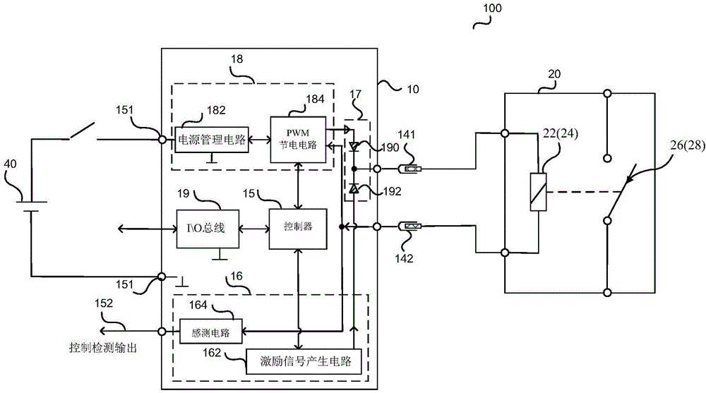
The invention discloses a connector and a contactor assembly. The connector is provided with a control circuit, and the control circuit is connected to a coil in a contactor and is used for controlling operations of the contactor; the control circuit includes a work control circuit for supplying work current to the contactor; the work control circuit includes a PWM power saving circuit which is connected to the contactor; when the contactor powers on, the PWM power saving circuit provides a signal with a preset duty ratio to the contactor (20); after the contactor (20) powers on, the PWM power saving circuit maintains that the PWM power saving circuit provides a signal with a small duty ratio to the contactor during the condition of power-on of the contactor (20) to reduce the power consumption. According to the connector and the contactor assembly, the PWM power saving circuit is integrated into the connector, so that the average drive current of the contactor is reduced, and the size of the contactor is reduced.

Description

technical field [0001] The present invention relates to a connector and a contactor assembly, and more particularly to a contactor, and a connector for connecting a coil in the contactor and controlling the operation of the coil. Background technique [0002] Contactors or relays are usually used to switch or control working circuits. For example, the contactor is provided with a coil and dynamic and static contacts. When current passes through the contactor coil, a magnetic field can be generated to close the dynamic and static contacts to control the load electrical appliances. [0003] Due to frequent switching on and off, the current conduction contacts of high-voltage and high-current contactors or relays will cause welding adhesion due to reasons such as overcurrent, high-temperature arc damage, or long-term application aging, so that the moving contacts of contactors or relays Ineffective out of control. For low voltage relays or contactors, general circuits can si...

Claims


Application Information

Patent Timeline
Patent Type & Authority Applications(China)
IPC IPC(8): H01H47/02H01H50/14
Inventor 周啸
Owner TYCO ELECTRONICS (SHANGHAI) CO LTD
Learn More