Energy conservation and emission reduction system with double back-pressure condensers in thermal power station

A thermal power plant, energy-saving and emission-reduction technology, applied in the direction of steam engine devices, machines/engines, mechanical equipment, etc., can solve the problems of low heat transfer efficiency and volume reduction of condensers, and achieve low ultimate pressure and suction pressure difference The effect of increasing and improving work efficiency

Inactive Publication Date: 2016-04-06
HUADIAN LAIZHOU POWER GENERATION
View PDF7 Cites 2 Cited by
  • Summary
  • Abstract
  • Description
  • Claims
  • Application Information

AI Technical Summary

Problems solved by technology

There are a large number of titanium tubes in the condenser, and the cooling water is circulated. When the exhaust steam of the steam turbine contacts the outer surface of the titanium tubes of the condenser, the temperature of the titanium tubes of the condenser is low due to the cooling of the water flow in the titanium tubes. When the exhaust steam of the steam turbine is in contact with the low-temperature titanium tube, the exhaust steam of the steam turbine releases latent heat of vaporization and turns into condensed water, and the latent heat released is continuously transferred to the circulating cooling water through the wall of the titanium tube and taken away. The volume shrinks sharply, forming a high vacuum in the condenser, uncondensed gas and air leaked in due to the loose connection of the condenser, resulting in low heat transfer efficiency of the condenser

Method used


Image

  • Energy conservation and emission reduction system with double back-pressure condensers in thermal power station
  • Energy conservation and emission reduction system with double back-pressure condensers in thermal power station

Examples


Embodiment Construction

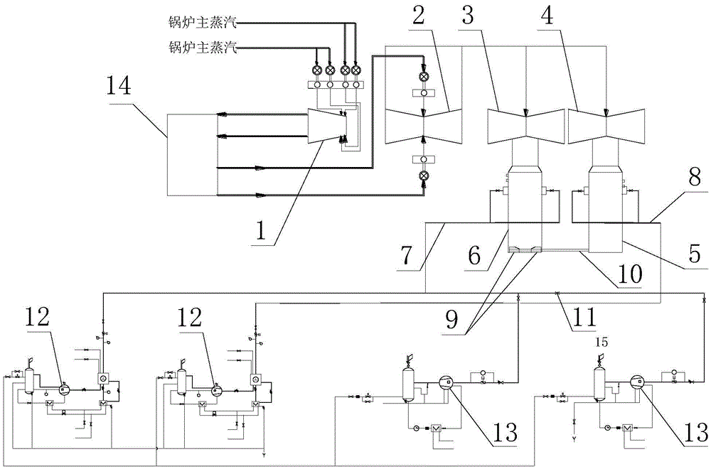
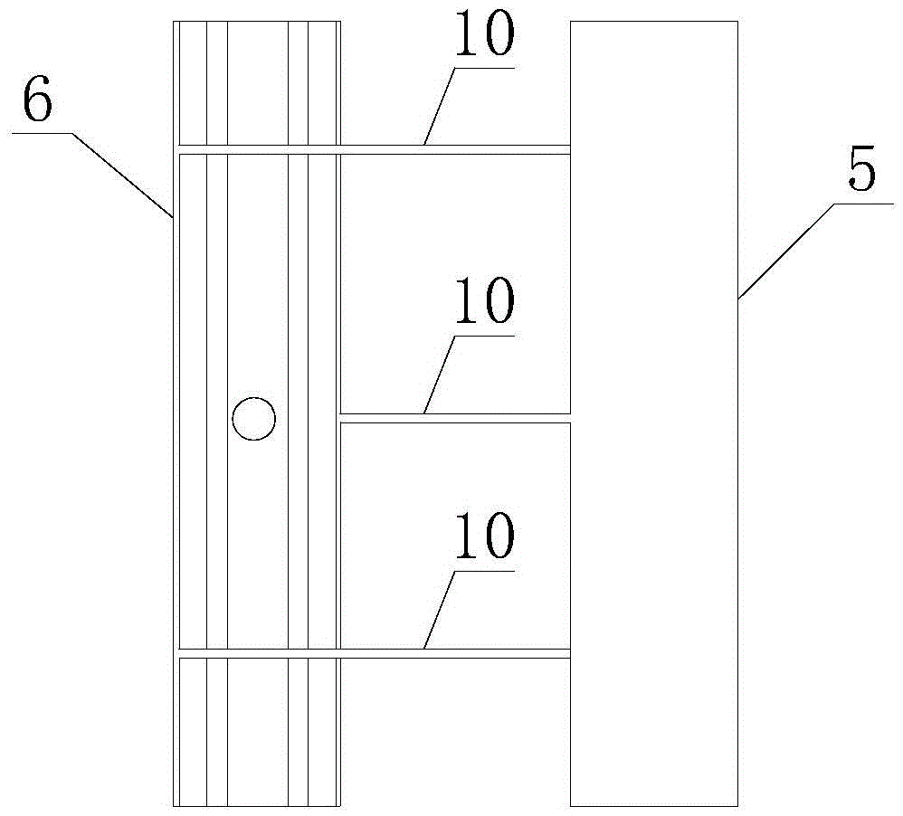
[0020] Embodiments of the present invention: as figure 1 and figure 2 As shown, an energy-saving and emission-reduction system with dual back pressure condensers in a thermal power plant includes a steam turbine high-pressure cylinder 1, a medium-pressure cylinder 2, A low-pressure cylinder 3, B low-pressure cylinder 4, a low-pressure condenser 5 and a high-pressure condenser 6. The steam turbine high-pressure cylinder 1 is connected to the medium-pressure cylinder 2, A low-pressure cylinder 3 and B low-pressure cylinder 4 are connected to the medium-pressure cylinder 2, A low-pressure cylinder 3 is connected to the high-pressure condenser 6, B low-pressure cylinder 4 is connected to the low-pressure condenser The condenser 5 is connected, the water side of the bottom of the low-pressure condenser 5 and the high-pressure condenser 6 are connected, and also includes a high-power water ring vacuum pump 12 and a three-stage Roots variable frequency pump group 13, a high-power wa...


PUM


Abstract

The invention discloses an energy conservation and emission reduction system with double back-pressure condensers in a thermal power station. The energy conservation and emission reduction system comprises a turbine high-pressure cylinder, an intermediate-pressure cylinder, a low-pressure cylinder A, a low-pressure cylinder B, the low-pressure condenser and the high-pressure condenser. The turbine high-pressure cylinder is communicated with the intermediate-pressure cylinder. The low-pressure cylinder A and the low-pressure cylinder B are communicated with the intermediate-pressure cylinder. The low-pressure cylinder A is communicated with the high-pressure condenser. The low-pressure cylinder B is communicated with the low-pressure condenser. The low-pressure condenser is communicated with the water side of the bottom of the high-pressure condenser. The energy conservation and emission reduction system further comprises high-power water ring vacuum pumps and three-level Roots variable frequency pump sets. The high-power water ring vacuum pumps and the three-level Roots variable frequency pump sets are communicated with an A side exhaust pipeline of the high-pressure condenser and a B side exhaust pipeline of the low-pressure condenser. According to the energy conservation and emission reduction system with the double-back-pressure condensers in the thermal power station, exhausting is conducted on the low-pressure condenser and the high-pressure condenser through the independently-operating exhaust pipelines respectively, the high-back-pressure condenser and the low-back-pressure condenser can operate in different exhaust pressure, compared with the manner that one exhaust mother pipe is used for two condensers, exhaust pressure of the low-pressure condenser is reduced, and the power capability of the low-pressure cylinders is improved.

Description

technical field [0001] The invention relates to the field of steam power generation, in particular to an energy-saving and emission-reduction system for double-backpressure condensers in thermal power plants. Background technique [0002] The steam flows through the high-pressure cylinder and the medium-pressure cylinder of the steam turbine in sequence, and enters the low-pressure cylinder A and the low-pressure cylinder B at the same time from the medium-pressure cylinder. The exhaust steam of the low-pressure cylinder A enters the high-pressure condenser, and the exhaust steam of the low-pressure cylinder B enters the low-pressure condenser. There are a large number of titanium tubes in the condenser, and the cooling water is circulated. When the exhaust steam of the steam turbine contacts the outer surface of the titanium tubes of the condenser, the temperature of the titanium tubes of the condenser is low due to the cooling of the water flow in the titanium tubes. When ...

Claims


Application Information

Patent Timeline
Patent Type & Authority Applications(China)
IPC IPC(8): F01K11/02
CPCF01K11/02
Inventor 刘彬张春杰王刚吴鲁东王洪刘培红
Owner HUADIAN LAIZHOU POWER GENERATION
Why Eureka
Try Eureka