
Robot hand with three under-actuated fingers connected in parallel

An underactuated and finger-based technology, applied in the field of robotics, can solve the problems of low stiffness and poor carrying capacity of parallel mechanisms, and achieve the effect of large working space, less degrees of freedom, and easy control

Active Publication Date: 2016-04-13
YANSHAN UNIV
View PDF14 Cites 6 Cited by
  • Summary
  • Abstract
  • Description
  • Claims
  • Application Information

AI Technical Summary

Problems solved by technology

The above-mentioned mechanisms have their own characteristics, but they also have the following disadvantages: the motion decoupling type parallel mechanism has low stiffness, and the load capacity in the motion decoupling direction is poor
Under the premise of ensuring the advantages of parallel robots, how to construct a parallel robot hand with three underactuated fingers to realize the flexible operation of fingers to grasp objects, and to ensure a large working space and dexterity has not been reported yet.

Method used


Image

  • Robot hand with three under-actuated fingers connected in parallel
  • Robot hand with three under-actuated fingers connected in parallel

Examples


Embodiment Construction

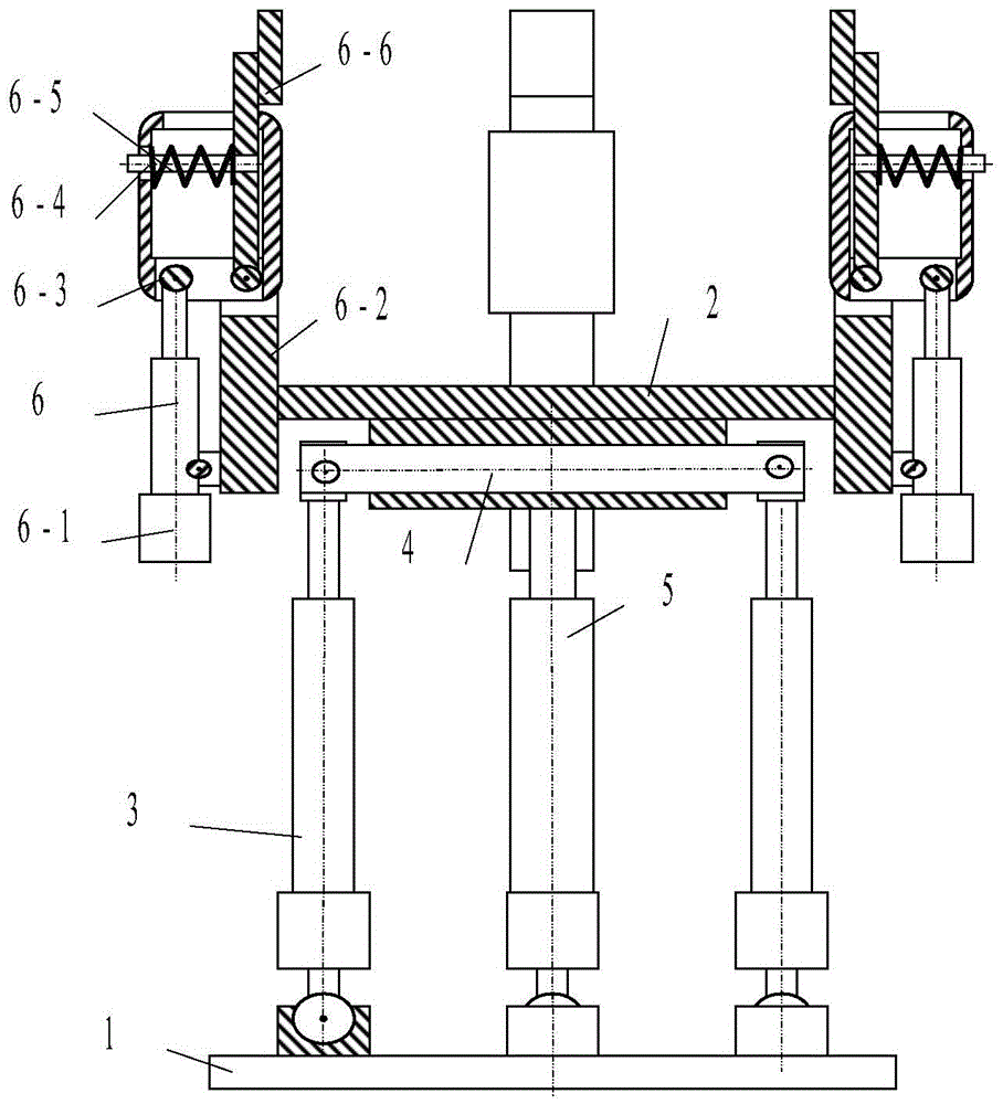
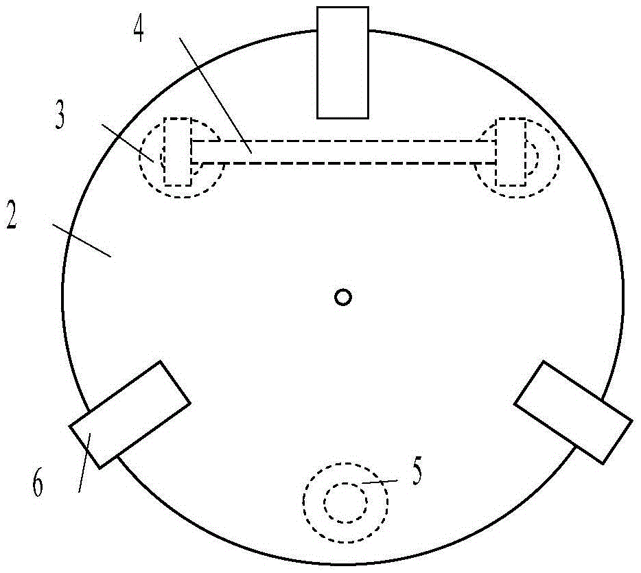
[0013] exist figure 1 and figure 2 In the schematic diagram of the parallel robot hand with three underactuated fingers shown, the three drive branches are all driven by conventional linear telescopic electric cylinders, and the three drive branches and the three underactuated finger mechanisms are formed between the moving platform and the machine base. Alternating circles are evenly distributed. Frame 1 is provided with 3 ball bearings uniformly distributed around the circumference; moving platform 2 is provided with 1 horizontal through hole and 1 vertical through hole; the middle part of connecting rod 4 is rotationally connected with the horizontal through hole of moving platform. The two ends of the connecting rod are respectively provided with through holes perpendicular to the axis of the connecting rod and parallel to each other; the upper end of the SP-type driving branch 5 is fixedly connected with the vertical through-hole of the above-mentioned moving platform, ...


PUM


Abstract

The invention provides a robot hand with three under-actuated fingers connected in parallel. The robot hand comprises a machine base, a movable platform, a connecting rod, an SP type drive branch, two SPR type drive branches and three under-actuated finger mechanisms. The three drive branches and the three under-actuated finger mechanisms are evenly distributed between the movable platform and the machine base in a staggered manner in the circumferential direction. The upper end of the SP type drive branch is fixedly connected with the movable platform. The lower end of the SP type drive branch is in linkage with machine base ball pairs. The two ends of the connecting rod are in linkage with the upper ends of the two SPR type drive branches. The middle portion of the connecting rod is in linkage with the movable platform. The lower ends of the SPR type drive branches are in linkage with the machine base ball pairs. Each under-actuated finger mechanism comprises a supporting frame, the finger, a spring, an electric cylinder and a support. The supports are vertically and fixedly connected with the movable platform. The fingers are connected with the supporting frames. The electric cylinders drive the supporting frames to rotate. The flexible object grabbing motion of the tail ends of the fingers is achieved through the springs between the supporting frames and the fingers. The robot hand is simple in structure, large in finger pose working space and good in flexibility, can achieve flexible grabbing operation and can be used for the outer space, the deep-sea detection, forging operation, rescue, medical treatment operation and the like.

Description

technical field [0001] The invention relates to the field of robots, in particular to a parallel robot hand. Background technique [0002] The parallel mechanism has the characteristics of large mechanism rigidity, strong bearing capacity, light end mass, small inertia, and no accumulation of position errors. It complements the advantages of serial robots in application. Compared with the six-degree-of-freedom parallel mechanism, the three-degree-of-freedom parallel mechanism has the advantages of simpler structure and easier control. It can be combined with a multi-underactuated finger mechanism to form a new type of parallel flexible hand. In recent years, it has attracted great attention from experts. . For the convenience of explanation, use n to represent the number of branches, use (S, U, P, R) to represent (ball pair, universal joint, moving pair, rotating pair) in the branch kinematic chain respectively, and their combination represents the structure of the branch k...

Claims


Application Information

Patent Timeline
Patent Type & Authority Applications(China)
IPC IPC(8): B25J9/00B25J15/10B25J15/12
CPCB25J9/0045B25J15/10B25J15/12
Inventor 路懿叶妮佳霍震杨路扬
Owner YANSHAN UNIV
Learn More