Sunlight control coating system with layer-side neutral reflection color and glass unit

A coating system and solar technology, applied in the field of glass parts, can solve the problems of unsightly and unsatisfactory vision, and achieve the effect of improving full utilization

Active Publication Date: 2016-04-13
VON ARDENNE ANLAGENTECHNIK GMBH
View PDF4 Cites 4 Cited by
  • Summary
  • Abstract
  • Description
  • Claims
  • Application Information

AI Technical Summary

Problems solved by technology

This is very visually unaesthetic and thus highly undesirable

Method used


Image

  • Sunlight control coating system with layer-side neutral reflection color and glass unit
  • Sunlight control coating system with layer-side neutral reflection color and glass unit
  • Sunlight control coating system with layer-side neutral reflection color and glass unit

Examples


Embodiment Construction

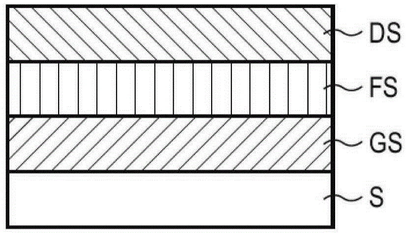
[0058] Solar control coating systems according to the prior art ( figure 1 ) looking upwards from the substrate S (6 mm thick glass) comprising the following coatings: Si 3 N 4 Composition of the underlying GS, layer thickness in the range of 9 to 17nm is composed of chromium carbide CrN x The composed functional layer FS and the top layer DS also composed of Si3N4 have a layer thickness in the range of 18 to 54 nm. This coating system achieves as Figure 4 The stated color values ​​and resistance values ​​of greater than 1000 Ω therefore classify the coating system according to the prior art as non-conductive.

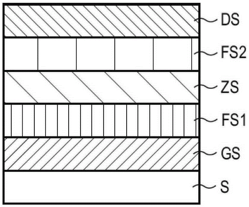
[0059] According to the first embodiment of the coating system of the present invention ( figure 2 ), on a glass substrate S with a thickness of 6 mm, the Si 3 N 4 Composition of the underlying GS. Immediately above it is a nickel-chromium nitride (NiCrN x ) or chromium carbide (CrN x ) composed of the first functional layer FS1. Arranged directly above the...


PUM


Abstract

The invention relates to a sunlight control coating system on an insulated transparent substrate and a glass unit. In order to enable such coating system to be provided as possible as much with neutral coating-side reflection color values and transmittance color values, the coating system includes at least the following coatings upwards viewed from the substrate: a silicon-containing dielectric base layer GS, a first functional layer FS 1, a dielectric intermediate layer ZS 1, a second functional layer FS 2, a silicon-containing dielectric top layer DS, wherein the intermediate layer ZS and / or the intermediate layer ZS are configured to be provided with low refractive indexes.

Description

technical field [0001] The present invention generally relates to a solar control coating system on an insulating transparent substrate and a glass part. Background technique [0002] Such solar control coating systems (hereinafter also simply referred to as coating systems) are applied to glass, for example by means of vacuum coating, and are mainly used in the architectural glazing industry for window and facade design as well as in the automotive industry. Its purpose is to reduce the total energy transmission g. The total energy is composed of solar radiation energy through the transmission of visible light (380nm to 780nm) and radiation in the wavelength range of near infrared light (approximately 780nm to 3μm) directly through the glass into the part of the room and the energy emitted inward due to the previous glass heating Composition, of which at most it is possible to emit what was previously absorbed. The smaller the g value, the better the shading effect. [0...

Claims


Application Information

Patent Timeline
IPC IPC(8): C03C17/34C03C17/36
CPCC03C17/36C03C17/3435C03C17/3639C03C17/3649C03C17/366
Inventor C·可科特M·贝伦特
Owner VON ARDENNE ANLAGENTECHNIK GMBH
Why Eureka
Try Eureka