Audio radiant tube as well as module and loudspeaker box provided with audio radiant tube
A radiation module and radiant tube technology, applied in frequency/direction characteristic devices, sensors, electrical components, etc., can solve the problem that the audio radiation port cannot be coaxially installed with the speaker unit, the sound wave interference and turbulence cannot be overcome, and the sound radiation resistance is large, etc. problems, to achieve the effect of wide range of use, wide applicability, sound field and pitch enhancement
- Summary
- Abstract
- Description
- Claims
- Application Information
AI Technical Summary
Problems solved by technology
Method used
Image

Examples
Embodiment 1
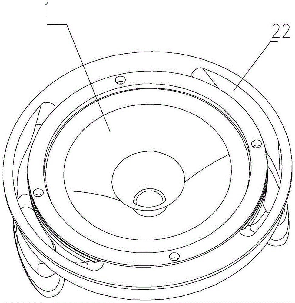
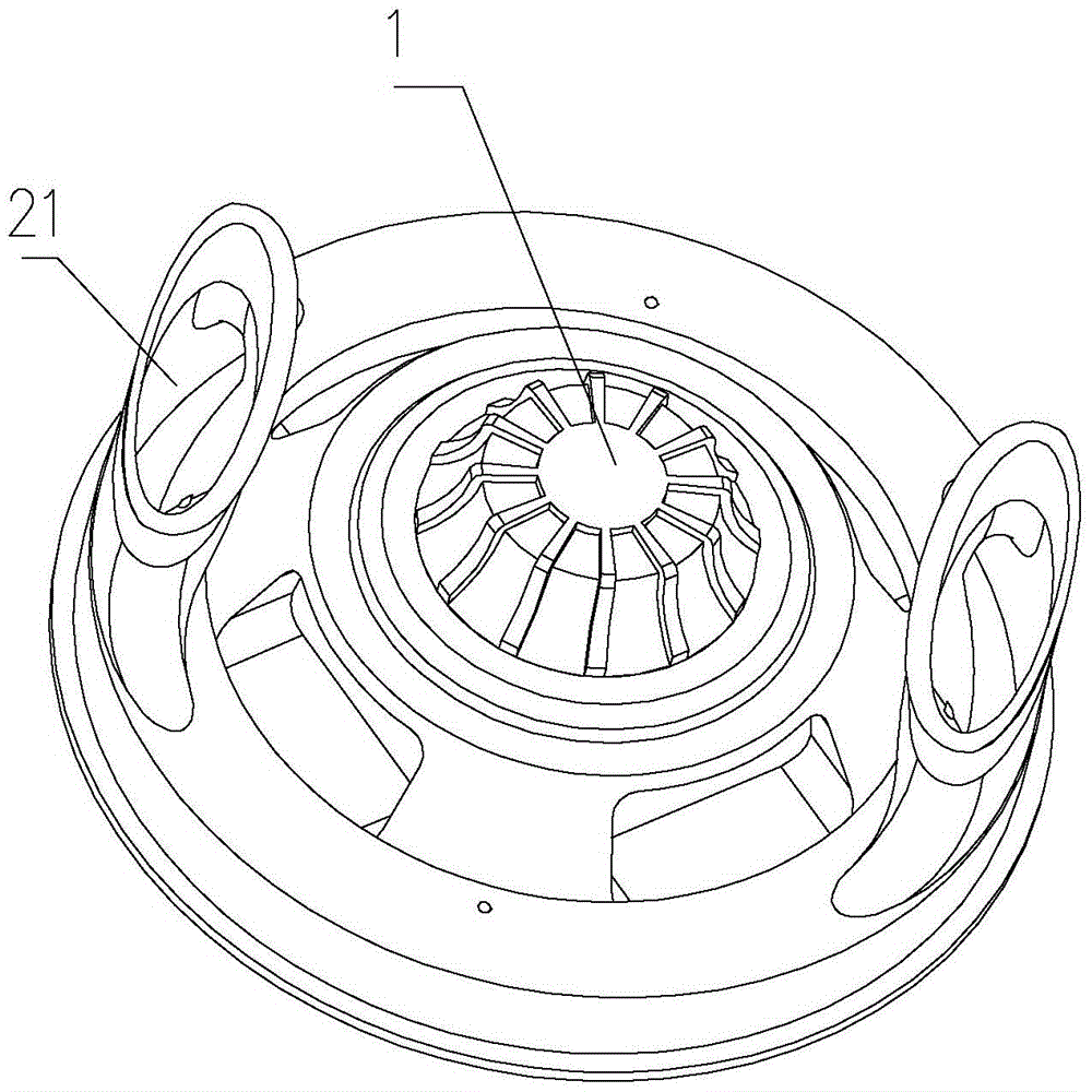
[0055] refer to Figure 1-4 , a compact audio inverter module, comprising: a speaker unit 1 and an audio radiation tube 2;
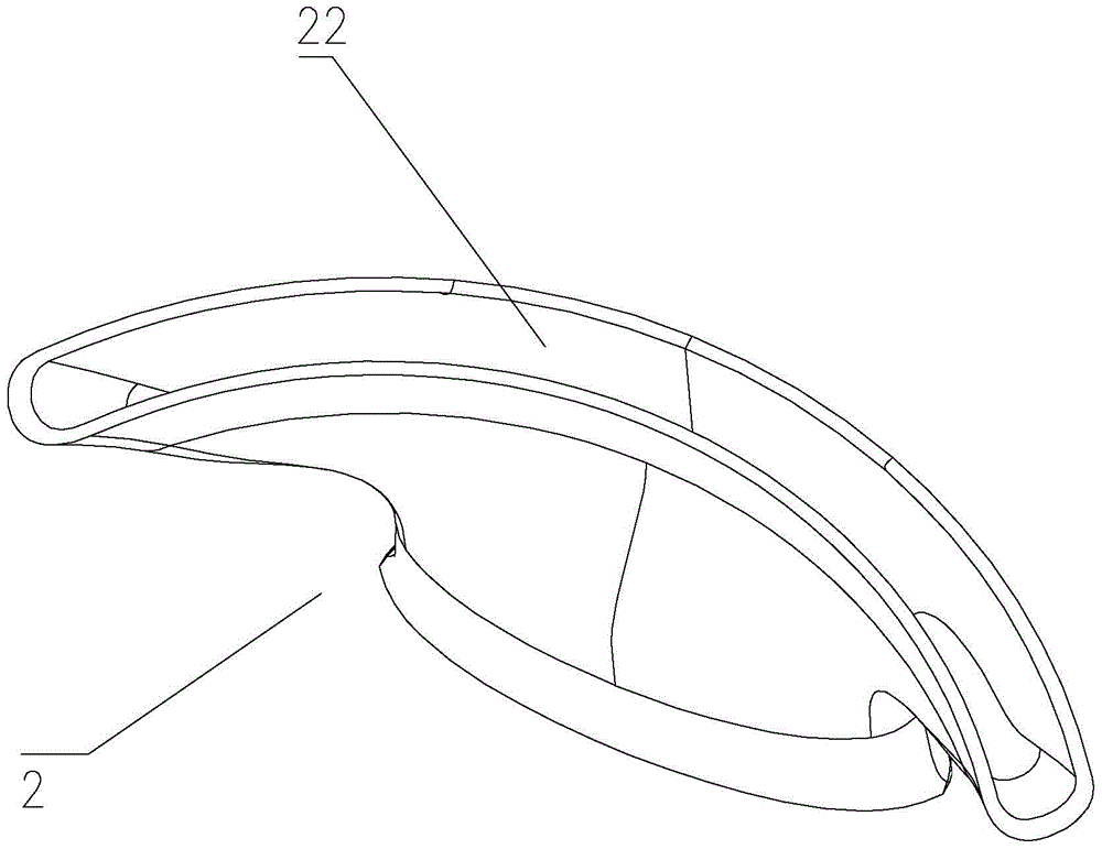
[0056] The audio radiation tube 2 includes an inlet port 21 connected to the rear of the speaker unit 1, and an arc-shaped outlet 22 located at the periphery of the sound cone of the speaker unit 1 and coaxially arranged therewith; therefore, the speaker unit 1 The rear sound wave is sent out from the outlet 22 after being phase-inverted by the audio radiation tube, and reaches approximately the same sound emission point as the speaker unit 1 . Therefore, the above-mentioned compact audio inverter module can achieve the effect of a full-range approximate point sound source, and the phase difference between high, medium and low frequency sounds is close to zero, and the sound field and pitch have been enhanced.
[0057] Since the sound wave propagating in the audio radiation tube 2 will be subject to interference and resistance, the interference and resist...
Embodiment 2
[0063] refer to Figure 5-6 The difference between this embodiment and Embodiment 1 is that there are two audio radiation tubes 2, and the total lengths of the two audio radiation tubes 2 are different. And the audio radiation tube 2 has a stretchable structure.
[0064] Therefore, when the compact audio inverter module is adapted to a smaller box, the length of the audio radiation tube 2 can be lengthened to match the smaller box volume. In order to match different volumes, different inverter tubes are required. Length, usually, multiple inverter tubes will be designed to be the same length, and will also be lengthened when lengthened. However, the inventors of the present invention have proved through experiments that the audio radiation tubes 2 can be of different lengths. At this time, two audio radiation tubes 2 of different lengths are combined to form one tube, which resonates with the cavity of the box body. The two inverter tubes are lengthened or shortened respecti...
Embodiment 3
[0066] refer to Figure 7-8 , the difference between this embodiment and embodiment 1 is:
[0067] The cross-sectional end of the inlet end 21 of the audio radiation tube is circular, and its diameter is smaller than the width of the outlet 22 along the arc distribution direction and larger than the radial width of the outlet 22 . For the audio phase inverter module using the large-size loudspeaker unit 1, its space is relatively large, and the cross-section of the inlet port 21 of the audio radiation tube can be designed as a circle to obtain the maximum cross-sectional area; It is also entirely feasible for the audio phase inverter module of the speaker unit 1 to continue to use an elliptical cross-sectional area design to obtain a more compact structure. .
PUM
 Abstract
Description
Claims
Application Information
 - R&D
- Intellectual Property
- Life Sciences
- Materials
- Tech Scout
- Unparalleled Data Quality
- Higher Quality Content
- 60% Fewer Hallucinations
Browse by: Latest US Patents, China's latest patents, Technical Efficacy Thesaurus, Application Domain, Technology Topic, Popular Technical Reports.
© 2025 PatSnap. All rights reserved.Legal|Privacy policy|Modern Slavery Act Transparency Statement|Sitemap|About US| Contact US: help@patsnap.com