Cardiac coronary artery stent

A technology for coronary arteries and hearts, applied in the cardiovascular field, can solve the problems of complex structure, high difficulty, and high processing difficulty, and achieve the effects of easy stent removal, direct and convenient manufacturing, and simple manufacturing process.

Active Publication Date: 2016-04-20
QIANFOSHAN HOSPITAL OF SHANDONG
View PDF11 Cites 8 Cited by
  • Summary
  • Abstract
  • Description
  • Claims
  • Application Information

AI Technical Summary

Problems solved by technology

Since the metal stent is usually engraved from a metal cylinder, and the surface of the cylinder is formed by a metal wire, when the metal stent is peeled off, the metal stent may be broken, making it difficult to clean the foreign matter at the incision site, and causing relatively large additional damage to the blood vessel. damage
[0007] For example, the Z-stent, the metal wire formed by the Z-stent is very thin, and the connection structure is sharp, sometimes it is very difficult for the guide wire to enter the branch through the gap of the stent
In addition, the Z-shaped stent is often a relatively long original tube, and a section is cut out to support the lesion. After cutting, there will be relatively sharp structures at both ends, which is very unfavorable for the insertion and removal of the stent.
[0008] Another example is the ring stent. The ring of the ring stent is not a ring, but a ring composed of a trapezoidal pulse waveform structure. Connectors need to be set between the rings. Usually, the connectors are generally waveform units, which can be understood as a whole. The units form a ring and are formed by connecting the rings with wave-shaped units. The structure is complex, and because it is still engraved by a metal cylinder as a whole, it is relatively difficult to process, and it is also more difficult to cut a section from the whole.
In addition, the expansion range of this type of stent is limited by the wavelength of the wave unit, and the axial bending performance is not good

Method used


Image

  • Cardiac coronary artery stent
  • Cardiac coronary artery stent
  • Cardiac coronary artery stent

Examples


Embodiment Construction

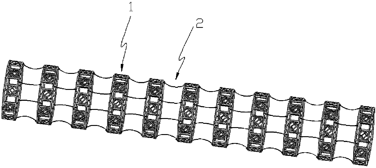
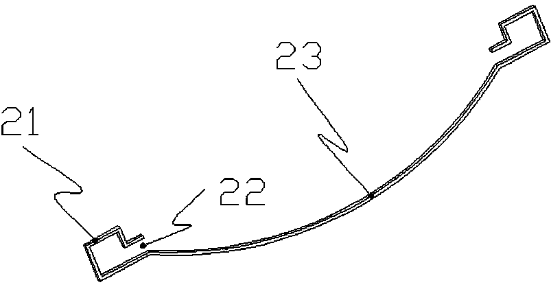
[0032] Refer to the attached figure 1 , figure 1 The middle is the assembly state of the vascular stent, which is a cylindrical structure as a whole, or a structure similar to a cylinder. Since the connecting body 2 is an elastic body, it has the ability to be bent to adapt to the physiological conditions of different vascular parts. structure.

[0033] If the heart coronary stent is regarded as a cylinder as a whole, the centrifugal and centripetal should be understood by those skilled in the art.

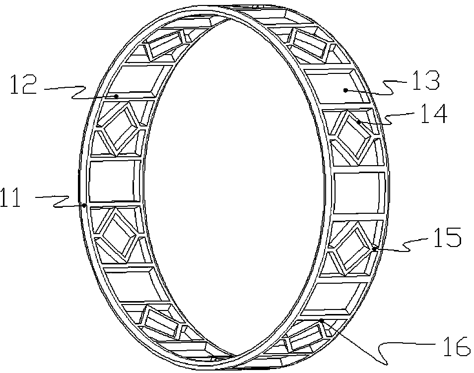
[0034] At the same time, the basic structure defined by the ring 1 is matched with a shaft, a ring, so that the circumferential direction and the axial direction should be understood by those skilled in the art.

[0035] See attached figure 1 , a heart coronary artery stent (hereinafter referred to as a stent for short) shown in the figure, its basic structure should include the following structures:

[0036] There are 11 rings 1 in the figure. It can be seen that ring 1 is th...


PUM

PropertyMeasurementUnit
lengthaaaaaaaaaa
thicknessaaaaaaaaaa
angleaaaaaaaaaa

Abstract

The invention discloses a cardiac coronary artery stent. The cardiac coronary artery stent comprises a plurality of rings and connectors. The two ends of each ring are end ring bodies formed by circular rings, and a plurality of connecting ribs are distributed in the circumference of the ring between the end ring bodies. Each connector comprises a linear elastomer and a joint arranged at each of the two ends of the elastomer. The joints are in buckle connection with the end ring bodies at the corresponding ends to be used for connecting the rings in sequence. According to the cardiac coronary artery stent, in some embodiments, the rings are divided by the connecting ribs circumferentially to form frame annular arrays with the ring axis serving as the shaft, wherein every two adjacent frames are different, space between the connecting ribs in one frame is larger than that between the connecting ribs in another frame. According to the cardiac coronary artery stent, the machining difficulty is low, but the use effect is good.

Description

technical field [0001] The invention relates to a cardiovascular, in particular to a tubular arterial stent in the cardiovascular. Background technique [0002] Vascular stents are widely used in interventional surgery, especially in cardiac interventional surgery, such as heart stent (Stent), which is mainly used for coronary artery interventional treatment, so it is also called coronary artery stent, mainly used to dredge coronary arteries. [0003] Currently used coronary stents mainly include metal stents, coated stents and soluble stents, wherein soluble stents are similar to metal stents in mechanical structure, but can be absorbed and dissolved by the body. In the present invention, the content involved is mainly It is the structure of the heart coronary artery stent, so whether it is soluble or not is not stated. Coated stents attach a layer of film to the outside of the metal stent to improve biocompatibility, and can also be combined with drugs to inhibit, for exa...

Claims


Application Information

Patent Timeline
Patent Type & Authority Applications(China)
IPC IPC(8): A61F2/07
CPCA61F2/07A61F2210/0004A61F2210/0014A61F2310/00023A61F2310/00029
Inventor 张明徐拥庆姜志明张众慧孙楠楠
Owner QIANFOSHAN HOSPITAL OF SHANDONG
Why Eureka
Try Eureka