A method of forming a water-blocking diaphragm wall with row piles and plug-in pile-plate combined support

A pile-plate combination and pile-plate technology, applied in sheet pile wall, foundation structure engineering, construction, etc., can solve the problems of high cost, large equipment investment, long construction period, etc., and achieve cost reduction, broad development space, reduction of The effect of material input

Active Publication Date: 2018-06-05
SHANDONG BEI TE LI FOUND ENG TECH CO LTD
View PDF9 Cites 0 Cited by
  • Summary
  • Abstract
  • Description
  • Claims
  • Application Information

AI Technical Summary

Problems solved by technology

[0002] With the rapid development of the national economy and infrastructure construction, the scale of foundation pit support and water-stop projects has been greatly increased. In order to save project cost and investment, and to improve the horizontal shear resistance of the support system and the anti-seepage of the water-stop structure In recent years, a large number of retaining wall support structures have been developed in China; the conventional retaining wall forms include: row pile walls, underground continuous walls, sheet pile walls, reinforced cement-soil walls, etc., row pile walls are generally cast-in-place piles, High-pressure rotary grouting piles are combined to form a continuous wall of piles. This method is used as a combination of support and anti-seepage. It is currently used on a large scale in domestic foundation pit support and anti-seepage projects. The investment in equipment is large and the energy consumption is high; the cement slurry loss during the construction of high-pressure rotary grouting piles is large, resulting in great waste of materials and environmental pollution; the joint construction of high-pressure jetting piles and cast-in-place piles is very strict on pile position deviation and verticality, such as Improper control often leads to quality defects at the junction of the two types of piles, which in turn affects the quality of the project. At the same time, due to the cross-construction of the two types of piles, restricted by site conditions and construction specifications, the general construction period is long, which is not conducive to the rapid development of the project. Therefore, the row pile wall has defects in terms of economy, quality, and construction period; the slab type underground diaphragm wall is the most widely used type of diaphragm wall at present. Advantages, it is currently widely used in subways, underground stations, shield and tunnel working shafts, industrial building sedimentation tanks and ultra-deep foundation pits, and has achieved good results; but the diaphragm wall has complex construction equipment, high cost, and mud pollution , Joint construction has quality defects, long construction period and other shortcomings; the existence of the slab diaphragm wall limits the popularization and utilization in the project due to the above problems; in summary, there are limitations in the selection of drilling rigs in the selection of construction equipment for pile walls and slab diaphragm walls , there are deficiencies in construction progress, quality, environmental protection, energy saving, application range, etc.; the above-mentioned construction methods need to be further innovated, improved, developed, and invented new construction methods on the basis of the original ones, so that the construction conditions and performance can be improved and enhanced. Achieve more significant social and economic benefits

Method used


Image

  • A method of forming a water-blocking diaphragm wall with row piles and plug-in pile-plate combined support
  • A method of forming a water-blocking diaphragm wall with row piles and plug-in pile-plate combined support
  • A method of forming a water-blocking diaphragm wall with row piles and plug-in pile-plate combined support

Examples


Embodiment 1

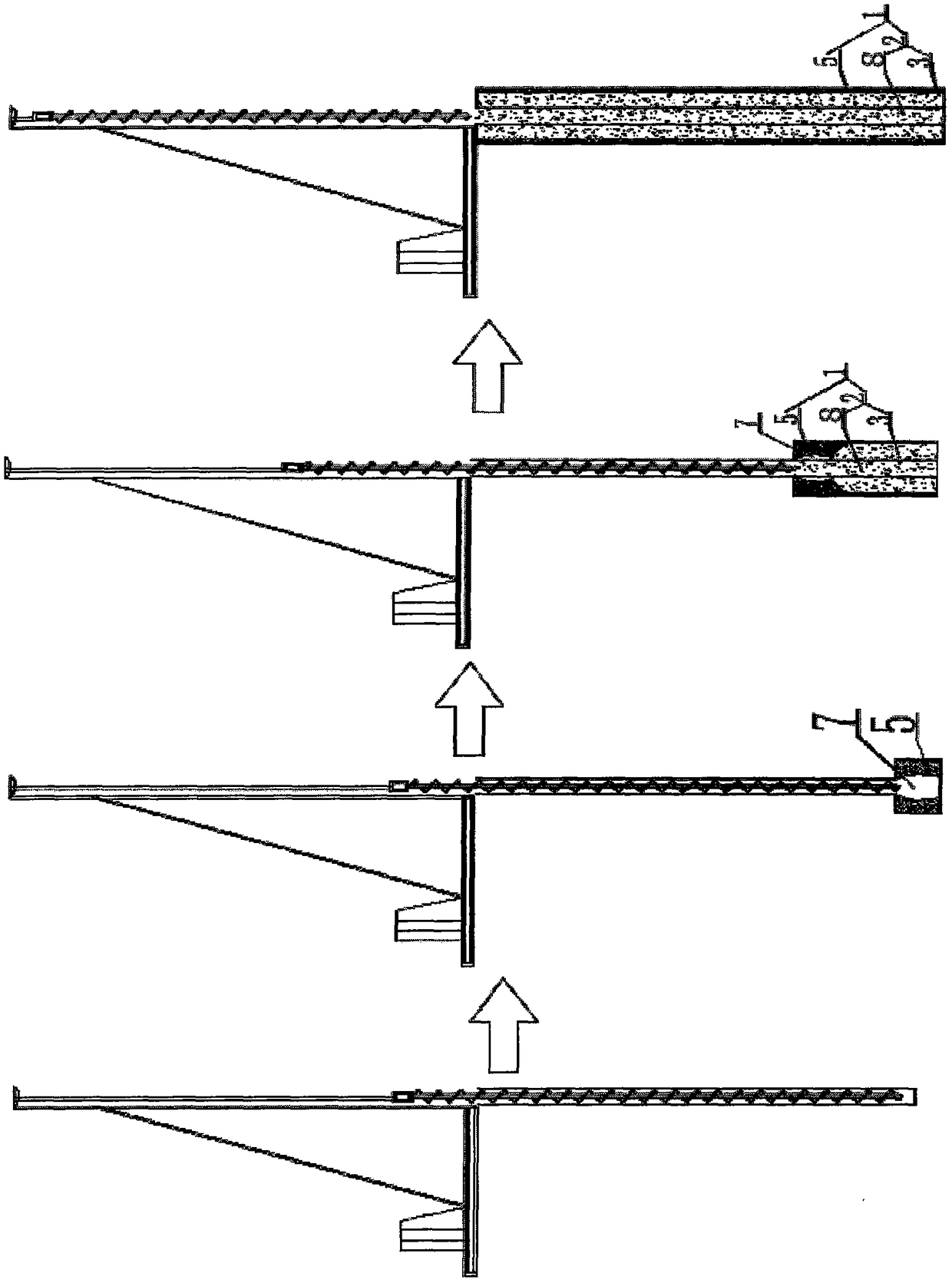
[0067] Such as figure 1 The row of piles inserted into the pile-slab combined type to support the water-blocking continuous wall, the long spiral drilled high-sprayed cement-soil composite plain concrete pile-slab composite pile includes a pile body 1, including a pile body 1, and the pile body 1 Consists of a pile body 2 and a cement-soil pile 5; a high-pressure rib cavity 7 is formed between the cement-soil pile 5 and the pile body 2; the high-pressure rib cavity 7 and the pile body 2 are expanded by concrete pressure filling ribbed concrete body 3; the expanded diameter ribbed concrete body 3 is arranged along the depth direction of the pile body 2; the plain concrete pile 8 is arranged inside the pile body 1; the plain concrete pile 8 is made of concrete pouring pile board and cement Composite soil piles.

[0068] A method for constructing a spiral-drilled high-sprayed cement-soil composite plain concrete pile-slab composite pile, comprising the following steps:

[0069]...

Embodiment 2

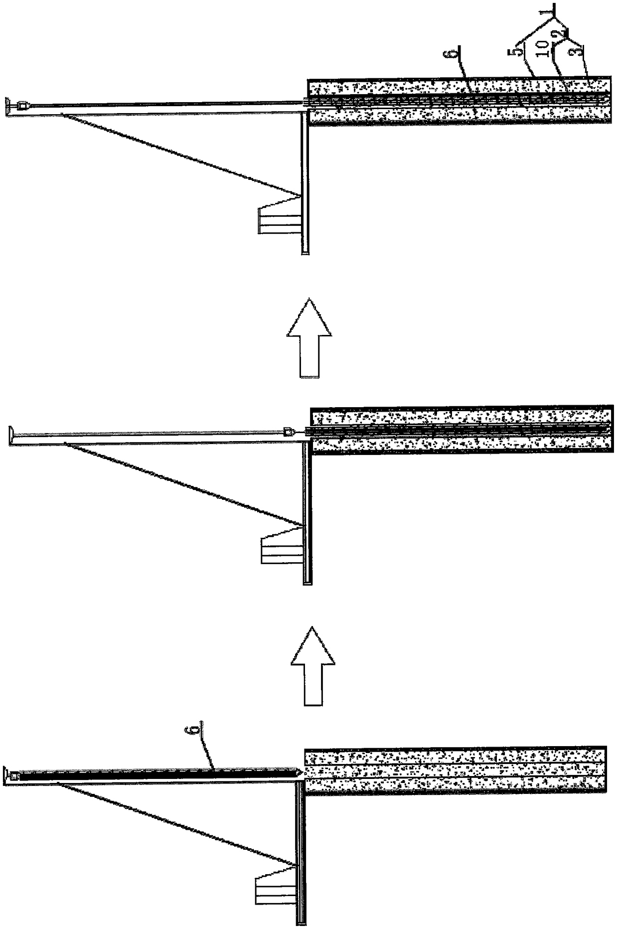
[0073] Such as figure 2 The row of piles inserted into the pile-slab combined type to support the water-blocking continuous wall, the long helical drilled high-sprayed cement-soil composite reinforced concrete pile-slab composite pile includes a pile body 1, including a pile body 1, and the pile body 1 Consists of a pile body 2 and a cement-soil pile 5; a high-pressure rib cavity 7 is formed between the cement-soil pile 5 and the pile body 2; the high-pressure rib cavity 7 and the pile body 2 are expanded by concrete pressure filling ribbed concrete body 3; the expanded diameter ribbed concrete body 3 is arranged along the depth direction of the pile body 2; the inside of the pile body 1 is provided with a reinforced concrete pile 10; the reinforced concrete pile 10 is made of a steel cage 6, concrete Pile board and cement-soil pile composite.

[0074] A construction method of spiral drilling high-sprayed cement-soil composite reinforced concrete pile-slab composite pile, co...

Embodiment 3

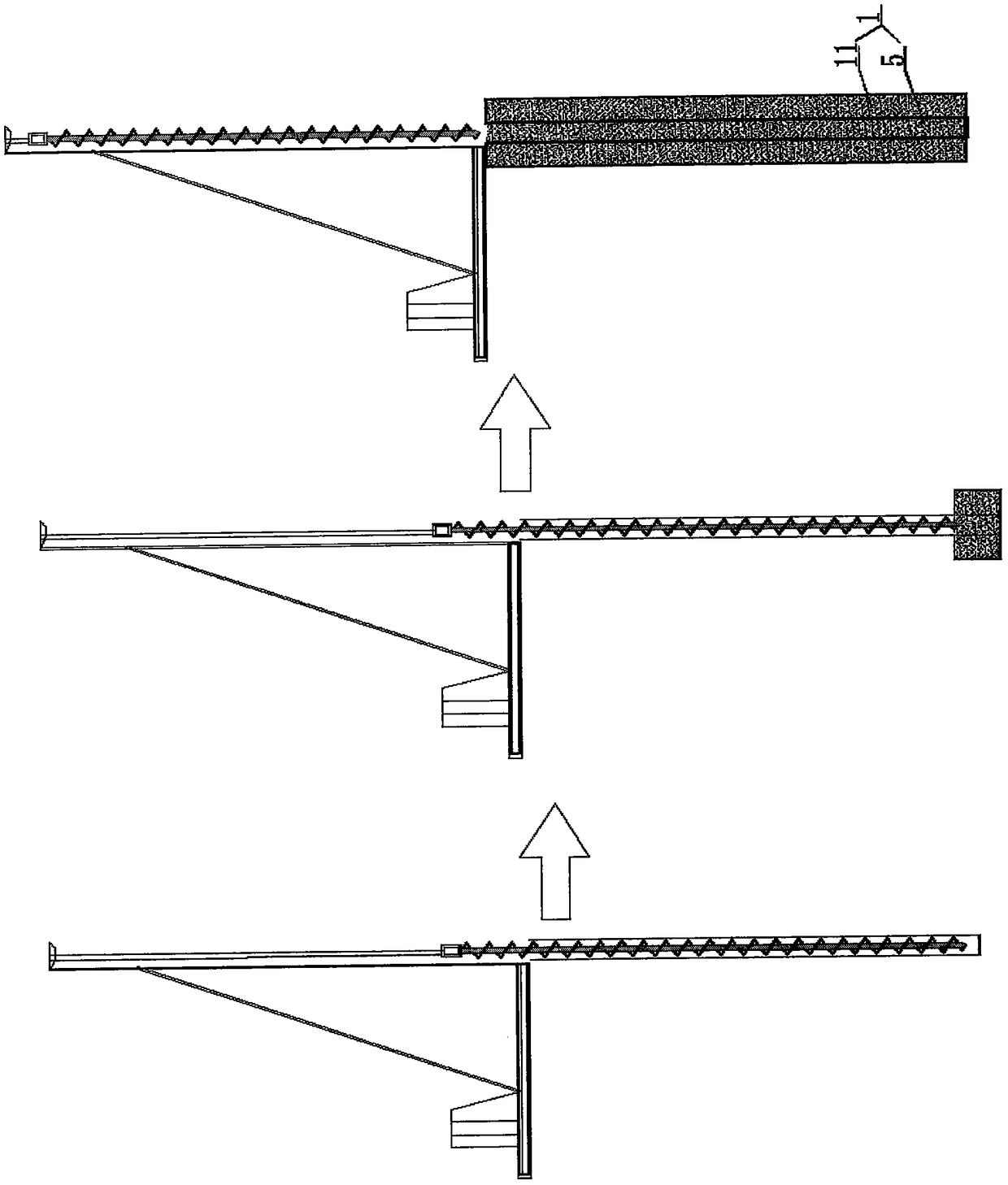
[0080] Such as image 3 The row of piles inserted into the pile-slab combined support water-blocking continuous wall, the long spiral drilled high-sprayed cement-soil pile slab includes a pile body 1, including the pile body 1, and the recently-mentioned pile body 1 is composed of cement-soil piles 5 It is composed of a cement-soil rib 11; the cement-soil rib 11 is arranged along the depth of the cement-soil pile 5.

[0081] A construction method of long helical drilling and high spray cement-soil pile slabs, comprising the following steps:

[0082] Step 1: Construction preparation. Before construction, prepare for three links and one leveling on the site, assemble and debug equipment on site, measure and set out lines, inspect lines, and check pile positions;

[0083] Step 2: Hole forming and high injection cement-soil pile slab construction, the drill bit of the multi-functional drilling rig is positioned at the set pile position, and after the multi-functional drilling rig...


PUM


Abstract

The invention discloses a campshed and inserted piled slab combined supporting water-plugging continuous wall forming construction method. The construction method particularly comprises the following construction methods: a campshed and inserted cement soil piled slab combined supporting water-plugging continuous wall forming construction method, a campshed and inserted concrete piled slab combined supporting water-plugging continuous wall forming construction method, a campshed and inserted concrete arch piled slab combined supporting water-plugging continuous wall forming construction method, and a campshed and inserted reinforced concrete arch piled slab combined supporting water-plugging continuous wall forming construction method. The campshed and inserted piled slab combined supporting water-plugging continuous wall forming construction method disclosed by the invention is small in equipment investment quantity and low in energy consumption, is cost-saving, has good structural shearing resistance and water-plugging seepage prevention performance, is short in construction period, is economic and environmental-friendly, has obvious comprehensive benefits.

Description

technical field [0001] The invention relates to a construction method of a diaphragm wall, in particular to a construction method of a continuous wall forming method for supporting water-blocking diaphragms with rows of piles inserted into pile plates, and belongs to the technical field of foundation construction engineering. Background technique [0002] With the rapid development of the national economy and infrastructure construction, the scale of foundation pit support and water-stop projects has been greatly increased. In order to save project cost and investment, and to improve the horizontal shear resistance of the support system and the anti-seepage of the water-stop structure In recent years, a large number of retaining wall support structures have been developed in China; the conventional retaining wall forms include: row pile walls, underground continuous walls, sheet pile walls, reinforced cement-soil walls, etc., row pile walls are generally cast-in-place piles, ...

Claims


Application Information

Patent Timeline
Patent Type & Authority Patents(China)
IPC IPC(8): E02D19/18E02D5/46E02D5/50
CPCE02D5/46E02D5/50E02D19/18E02D2300/002
Inventor 李金良
Owner SHANDONG BEI TE LI FOUND ENG TECH CO LTD
Why Eureka
Try Eureka