An emergency release device for a gas cabinet

A gas tank and emergency technology, which is applied in the field of emergency venting devices for gas tanks, can solve problems such as gas leakage, easy corrosion, hidden safety hazards, etc., and achieve the effects of saving man-hours and costs, strengthening sealing effect, and facilitating coordination and positioning.

Active Publication Date: 2017-11-21
WISDRI ENG & RES INC LTD
View PDF6 Cites 0 Cited by
  • Summary
  • Abstract
  • Description
  • Claims
  • Application Information

AI Technical Summary

Problems solved by technology

This type of device has the following problems: 1) when the relief valve 10 is released, the high-speed airflow will form a strong impact on the relief valve 10, sometimes causing serious vibration and noise on the valve body; 2) the device requires high installation accuracy, Otherwise, the phenomenon of "stuck" may occur during operation; 3) the key equipment such as the relief valve 10 is exposed to the atmospheric environment for a long time, which is easy to corrode and wear; 4) the sealing effect of the bonnet of the relief valve 10 is not satisfactory , there is a possibility of gas leakage, and there is a certain potential safety hazard; 5) The device is complicated and the cost is high
This type of device has the following problems: 1) a certain amount of sealing oil 13 will inevitably leak out during emergency release, and it is difficult to recover, which not only causes economic losses, but also pollutes the site environment; 2) the system cannot be manually opened for emergency release, There are certain hidden dangers; 3) The release pipe 2 is exposed to the atmospheric environment for a long time, and it is easy to corrode, and its corrosion products accumulate in the opening 14 of the side plate 1 of the cabinet, which is easy to block the release channel; 4) The side plate 1 of the cabinet needs to be Opening holes will have an adverse effect on the structural performance of the side panel 1 of the cabinet

Method used


Image

  • An emergency release device for a gas cabinet
  • An emergency release device for a gas cabinet
  • An emergency release device for a gas cabinet

Examples


Embodiment Construction

[0032] The present invention will be further described below in conjunction with the accompanying drawings and embodiments.

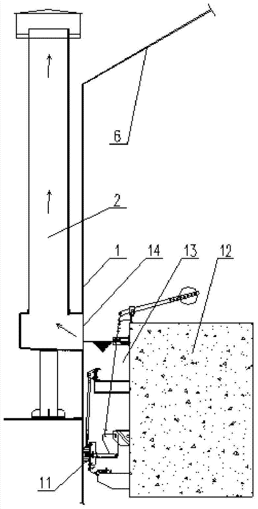
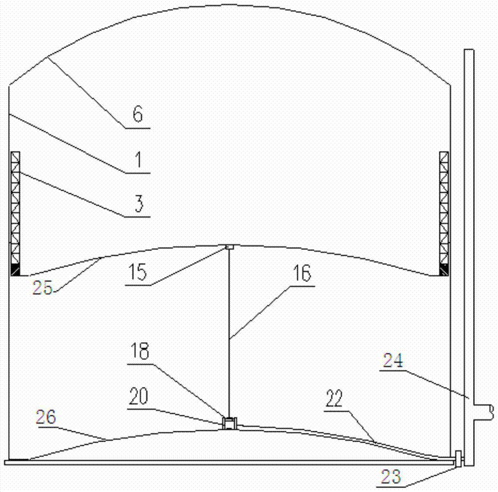
[0033] Such as image 3 and Figure 4 As shown, an emergency relief device for a gas cabinet includes a steel rope 16, a relief valve, a first relief pipe 22 and a safety relief pipe 24. The relief valve is composed of a valve seat 20 and a valve cover 18, and the valve seat 20 is provided with an opening at the top The valve cover 18 can completely cover and seal the top opening of the valve seat 20, the valve seat 20 is fixed on the cabinet bottom plate 26, the two ends of the steel rope 16 are respectively connected with the piston plate 25 and the valve cover 18, and the steel rope 16 The effective length is equal to the stroke of the piston, and one end of the first relief pipe 22 communicates with the valve seat 20, and the other end passes through the gas tank and communicates with the safety relief pipe 24. Such as image 3 As shown, under no...


PUM


Abstract

The invention relates to an emergent diffusion device of a gas holder. The device comprises a steel rope, a diffusion valve, a first diffusion pipe and a safe diffusion pipe; the diffusion valve consists of a valve base and a valve cover; the valve base is a container provided with an opening in the top; the valve cover can totally cover and seal the opening in the top of the valve base; the valve base is fixed on a holder baseplate; two ends of the steel rope are respectively connected with a piston plate and the valve cover; the effective length of the steel rope is equal to the travel of a piston; and one end of the first diffusion pipe is communicated with the valve base, and the other end is communicated with the safe diffusion pipe after penetrating out of the gas holder. The device is simple in structure, low in cost and safe in operation; and the diffusion valve is put in the gas holder to achieve the effects of long service life and good noise absorbing effect.

Description

technical field [0001] The invention belongs to the field of gas cabinet design, in particular to an emergency release device for a gas cabinet. Background technique [0002] Gas cabinets are widely used in the recovery and storage of by-product gas in iron and steel enterprises. Its main principle is to realize gas in and out through the up and down movement of the piston. [0003] Generally, the gas cabinet is equipped with an emergency release device, which is one of the preventive measures to prevent the accident of the piston overrunning. Running the last line of defense is again very necessary. [0004] Existing emergency release devices for gas holders are mainly divided into two categories. [0005] One is the emergency release device of the rubber membrane sealed dry gas holder, such as figure 1 As shown, it mainly includes a release valve 10, a steel rope 9, a steel rope pulling mechanism 8, a piston automatic jacking mechanism 4, a push rod 5 and a manual open...

Claims


Application Information

Patent Timeline
Patent Type & Authority Patents(China)
IPC IPC(8): F17B1/12
CPCF17B1/12
Inventor 付重重黄永红
Owner WISDRI ENG & RES INC LTD
Why Eureka
Try Eureka