Transient electromagnetic transmitter circuit with load in parallel connection for discharging

A transient electromagnetic and transmitter technology, applied in the direction of sound wave re-radiation, electromagnetic/magnetic exploration, utilization of re-radiation, etc. Turn-off delay, increase the equivalent magnetic moment, reduce the effect of transient electromagnetic detection blind area

Inactive Publication Date: 2016-04-20
JILIN UNIV
View PDF5 Cites 15 Cited by
  • Summary
  • Abstract
  • Description
  • Claims
  • Application Information

AI Technical Summary

Problems solved by technology

In addition, when detecting geological information at a deeper level (below 1km), it is necessary to generate a larger magnetic moment, which can be achieved by increasing the emission curren...

Method used


Image

  • Transient electromagnetic transmitter circuit with load in parallel connection for discharging
  • Transient electromagnetic transmitter circuit with load in parallel connection for discharging
  • Transient electromagnetic transmitter circuit with load in parallel connection for discharging

Examples


Embodiment Construction

[0021] Below in conjunction with accompanying drawing and embodiment the present invention is described in further detail:

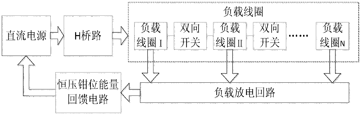
[0022] The transient electromagnetic transmitter circuit for load parallel discharge, including DC power supply, H bridge circuit, load coil, bidirectional switch, load discharge circuit and constant voltage clamp circuit, is composed of DC power supply through H bridge circuit, load coil Ⅰ, bidirectional switch Ⅰ. Load coil Ⅱ and bidirectional switch Ⅱ... are connected to load coil N. Load coil Ⅰ, load coil Ⅱ.... and load coil N are respectively connected to load discharge circuit, and the load discharge returns to the constant voltage clamp energy feedback circuit and DC power connection constitutes.

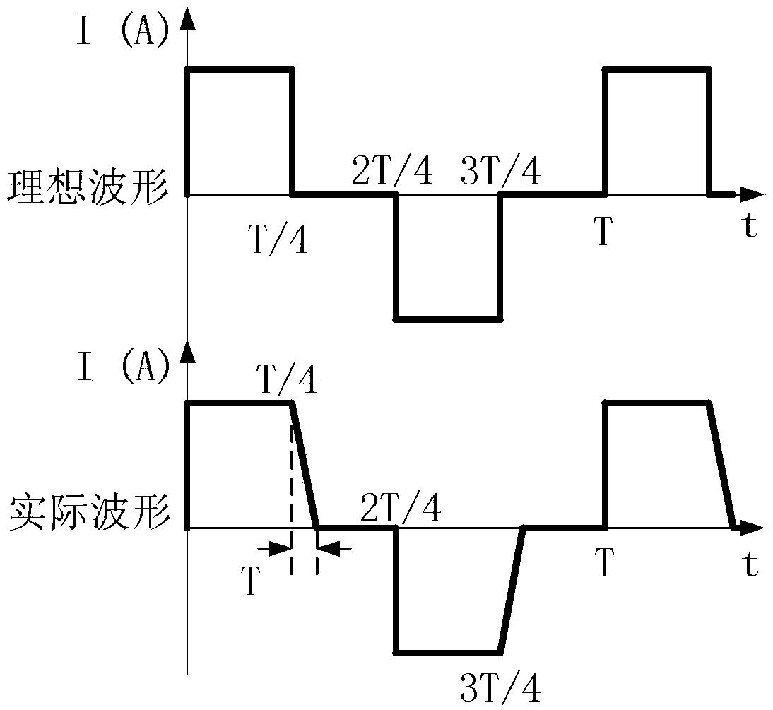
[0023] The bidirectional switch is connected with each turn of the load coil, so that the load coil is in a series state when the current rises and stabilizes, and the coil is in a parallel state when the current is discharged.

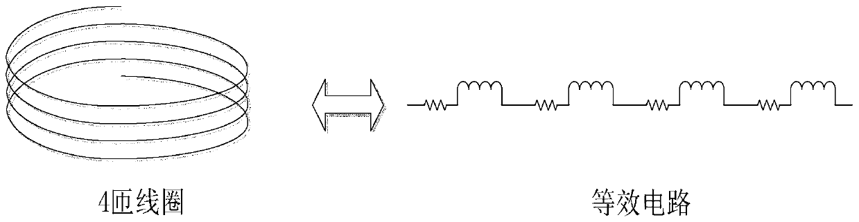
[0024] Each coil consis...


PUM


Abstract

The invention relates to a transient electromagnetic transmitter circuit with loads in parallel connection for discharging. The transient electromagnetic transmitter circuit comprises a DC power supply, an H bridge circuit, load coils, bidirectional switches, a load discharging loop and a constant-voltage clamping circuit, wherein the DC power supply is connected with the load coil N through the H bridge circuit, the load coil I, the bidirectional switch I, the load coil II, the bidirectional switch II...; the load coil I, the load coil II,...and the load coil N are each connected with the load discharging loop; and the load discharging loop is connected with the DC power supply through the constant-voltage clamping circuit. Compared with the prior art, by adopting the bidirectional switches and diodes, the load coils are in a series connection state when the current rises and is stable, and the load coils are in parallel connection state in discharging. The transient electromagnetic transmitter circuit effectively reduces equivalent inductance of the loads in discharging, reduces turn-off delay time of the transmitter, and reduces transient electromagnetic detection blind zone. The load coil segmentation method is flexible, and parallel load inductance value can be changed according to specific detection requirements. Under the condition of same turn-off delay time, the transmitting current or load coil number can be increased, the equivalent magnetic moment is enlarged, and the detection depth and resolution are increased.

Description

technical field [0001] The invention relates to a transient electromagnetic detector circuit in geophysical exploration, in particular to a transient electromagnetic transmitter circuit applicable to various power levels. Background technique [0002] Transient electromagnetic detection instruments are widely used in the field of geophysical detection, and usually consist of a transmitter and a receiver. The detection depth and detection accuracy are not only related to the sampling speed, dynamic range, noise performance of the receiver, but also to the transmitter It is related to factors such as emission current, turn-off time, and turn-off waveform. The working principle is as follows, the inductive load formed by the transmitter to the multi-turn wire (as attached figure 2 shown) to send a bipolar current waveform (as attached image 3 As shown), the primary pulse magnetic field is excited, and the primary field propagates underground and excites the underground condu...

Claims


Application Information

Patent Timeline
IPC IPC(8): G01V3/00
CPCG01V3/00
Inventor 于生宝陈旭韩哲鑫李齐刘伟宇孙长玉
Owner JILIN UNIV
Why Eureka
Try Eureka