
Optical fiber connector and assembly method thereof

A technology of optical fiber connector and optical fiber, applied in the coupling of optical waveguide, etc., can solve the problems of short length of stress buffer boots, easy damage of optical cables, large number of parts, etc., and achieve the advantages of small total length, reduced quantity and simplified structure Effect

Active Publication Date: 2016-04-20
TYCO ELECTRONICS (SHANGHAI) CO LTD
View PDF5 Cites 3 Cited by
  • Summary
  • Abstract
  • Description
  • Claims
  • Application Information

AI Technical Summary

Problems solved by technology

[0005] In the aforementioned optical fiber connectors in the prior art, the number of independent components included in the optical fiber connector is relatively large, and the structure is also very complicated, which is not convenient for quick installation of the optical fiber connector on site, and it is very time-consuming to assemble the optical fiber connector on site
[0006] Moreover, in the prior art, due to the need to use a longer extension tube, this will cause the overall length of the optical fiber connector to be too long, and the length of the stress buffer boot to be too short, which will cause the optical cable connected to the optical fiber connector to be Susceptible to damage when subjected to lateral pull, i.e., reduces the ability of the cable to resist lateral loads
[0007] In addition, in the prior art, it is necessary to use a special crimping tool to crimp the crimping sleeve or the stress buffer shoe on the rear end of the extension tube, which increases the difficulty of assembling the optical fiber connector on site

Method used


Image

  • Optical fiber connector and assembly method thereof
  • Optical fiber connector and assembly method thereof
  • Optical fiber connector and assembly method thereof

Examples


no. 1 example

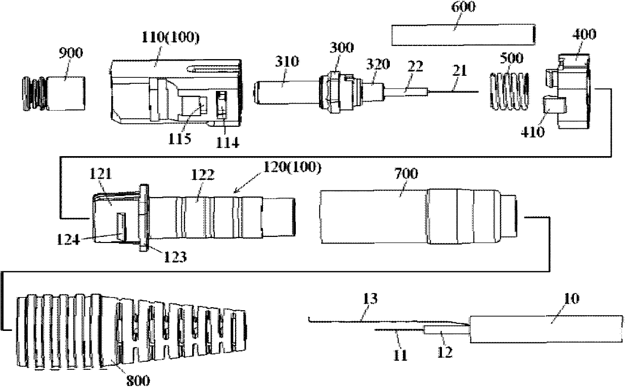
[0072] figure 1 An exploded view of the optical fiber connector according to the first exemplary embodiment of the present invention is shown, wherein the outer housing 200 is not shown.

[0073] Such as figure 1 As shown, in an exemplary embodiment of the present invention, an optical fiber connector mainly includes an inner housing 100 , an outer housing 200 , a ferrule assembly, a spring 500 , a heat shrinkable tube 700 and a stress buffer shoe 800 .

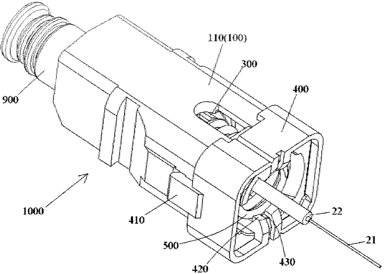
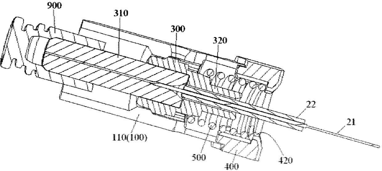
[0074] Figure 10 A schematic diagram showing a complete optical fiber connector formed after fitting the stress buffer boot 800 onto the heat shrink tube 700 and the optical cable 10 and installing the inner housing 100 into the outer housing 200; Figure 11 show Figure 10 Cutaway view of the fiber optic connector shown.

[0075] Such as figure 1 , Figure 10 and Figure 11 As shown, in the illustrated embodiment, the ferrule assembly is housed in the inner housing 100 , and the ferrule assembly includes a ferrule 30...

no. 2 example

[0109] Figure 12 shows a cross-sectional view of an optical fiber connector according to a second exemplary embodiment of the present invention, wherein the outer housing is not shown; and Figure 13 show Figure 12 A cutaway view of the fiber optic connector is shown, where the outer housing and fiber optic cable are not shown.

[0110] Figure 12 and Figure 13 Shown is a second embodiment of the fiber optic connector with Figure 1 to Figure 11 The main difference of the optical fiber connector of the first embodiment shown is the fixing structure of the Kevlar fiber used to fix the optical cable. besides, Figure 12 and Figure 13 Shown is a second embodiment of the fiber optic connector with Figure 1 to Figure 11 The optical fiber connectors of the first embodiment shown are basically the same, and for the sake of brevity, only the differences between the first embodiment and the second embodiment will be described below.

[0111] Such as Figure 12 and Figur...


PUM


Abstract

The invention discloses an optical fiber connector comprising an outer housing, an inner housing, a core-inserting assembly, and a spring. The inner housing is disposed in the outer housing. The core-inserting assembly is accommodated in the inner housing, and comprises a core-inserting body and a preset optical fiber disposed in the core-inserting body. The spring is accommodated in the inner housing, and is disposed on the rear part of the core-inserting body, and is used to apply the preset axial force to the core-inserting body. The inner housing comprises a front body and a rear body, and the rear body is disposed on the front body. The spring is disposed between the rear body and the core-inserting body in a compressed manner. According to the invention, the rear body can be used as the retainer for compressing the spring and the extension pipe for fixing the Kevlar fiber of the optical cable, and therefore compared to the prior art, the number of the parts of the optical fiber connector can be reduced, the structure of the optical fiber connector can be simplified, and the on-site quick assembly of the optical fiber connector can be facilitated.

Description

technical field [0001] The invention relates to an optical fiber connector and an on-site assembly method of the optical fiber connector. Background technique [0002] In the prior art, a fusion-type optical fiber connector connected to one end of an optical cable through optical fiber fusion generally includes an inner housing, an outer housing, a ferrule assembly, a spring, a spring retainer, an optical cable fixing assembly, and a protective cover for a fusion point tubes, strain relief boots and dust caps. The aforementioned ferrule assembly includes a ferrule and a section of preset optical fiber held in the ferrule, and the preset optical fiber is used for heat fusion with the incoming optical fiber of the optical cable. [0003] In the prior art, when assembling optical fiber connectors on site, it is necessary to install the dust cap, ferrule assembly, spring and spring retainer into the inner housing one by one; Splice together; then splice the fusion point protec...

Claims


Application Information

Patent Timeline
Patent Type & Authority Applications(China)
IPC IPC(8): G02B6/255G02B6/38
Inventor 王黎明胡贯朋陆友锋
Owner TYCO ELECTRONICS (SHANGHAI) CO LTD
Learn More