
A method and system for detecting power sag based on different-zone aerial images

An aerial image and detection method technology, applied in three-dimensional position/channel control and other directions, can solve the problems of inability to take into account the accuracy, cost and efficiency of measurement, slow manual detection speed, large data processing volume, etc., and achieves short data preprocessing time. , the effect of low operation cost and high collection efficiency

Active Publication Date: 2018-02-09
航天远景空间地理信息(深圳)有限公司
View PDF10 Cites 0 Cited by
  • Summary
  • Abstract
  • Description
  • Claims
  • Application Information

AI Technical Summary

Problems solved by technology

Both of the above two methods have obvious disadvantages. The sag is observed by the gear end angle method. The manual detection speed is slow and the efficiency is low. It can only measure the lowest sag point. Radar measurement, expensive equipment, high cost, large amount of data processing, low efficiency, accuracy to centimeter level
It can be seen that the above two methods cannot take into account the accuracy, cost and efficiency of measurement

Method used


Image

  • A method and system for detecting power sag based on different-zone aerial images
  • A method and system for detecting power sag based on different-zone aerial images
  • A method and system for detecting power sag based on different-zone aerial images

Examples


Embodiment 1

[0018] Embodiment 1, a kind of power sag detection method based on different-band aerial images, the following will be combined with the attached figure 1 A power sag detection method based on out-of-band aerial images of the present invention is described in detail.

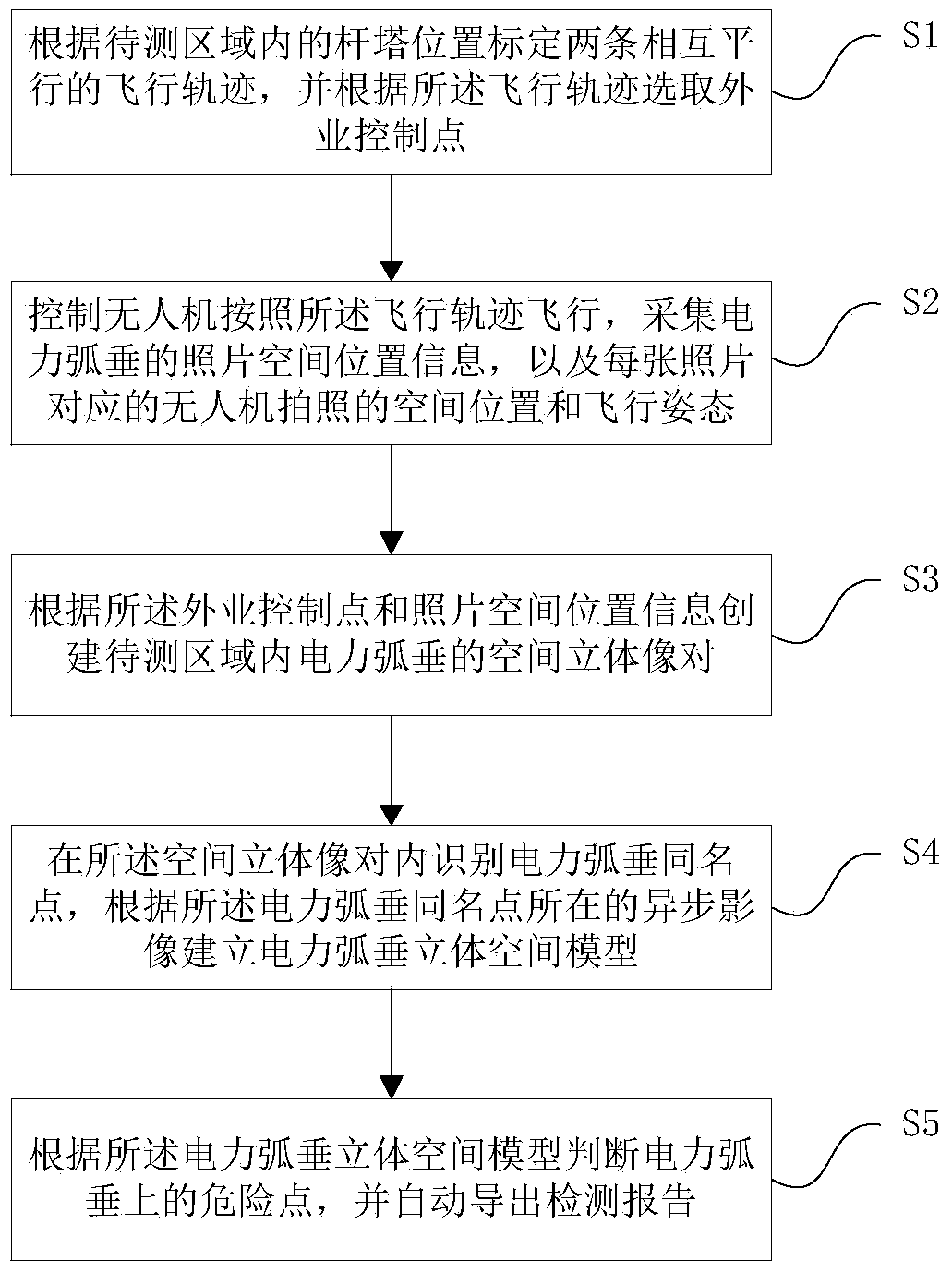
[0019] Such as figure 1 As shown, a flow chart of a power sag detection method based on different-zone aerial images, including:

[0020] Step 1: Calibrate two mutually parallel flight trajectories according to the position of the tower in the area to be measured, and select field control points according to the flight trajectories;

[0021] Step 2: Control the UAV to fly according to the flight trajectory, and take pictures at the same time to collect the photo space position information of the power sag in the area to be measured, and the space position and flight attitude of the UAV photo corresponding to each photo;

[0022] Step 3: Create a spatial three-dimensional image pair of power sag in the area to ...

Embodiment 2

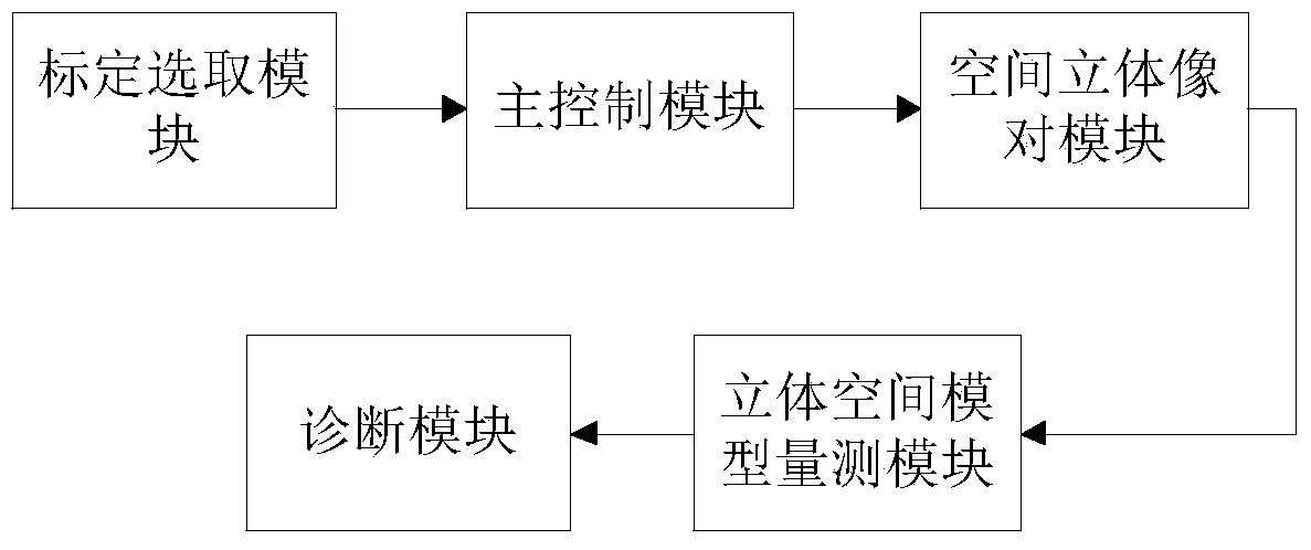
[0033] Embodiment 2, a kind of power sag detection system based on different-band aerial images, the following will be combined with the attached image 3 A power sag detection system based on out-of-band aerial images of the present invention is described in detail.

[0034] Such as image 3 As shown, a schematic diagram of the structure of a power sag detection system based on different-zone aerial images, including a calibration selection module, a main control module, a spatial stereo image pair module, a stereo space model measurement module, and a diagnosis module.

[0035]Wherein, the calibration selection module is used to receive the position of the tower in the area to be measured from the outside, calibrate two mutually parallel flight trajectories according to the position of the tower, and automatically select the field control point according to the flight trajectories; the main control module It is used to control the UAV to fly according to the flight trajecto...


PUM


Abstract

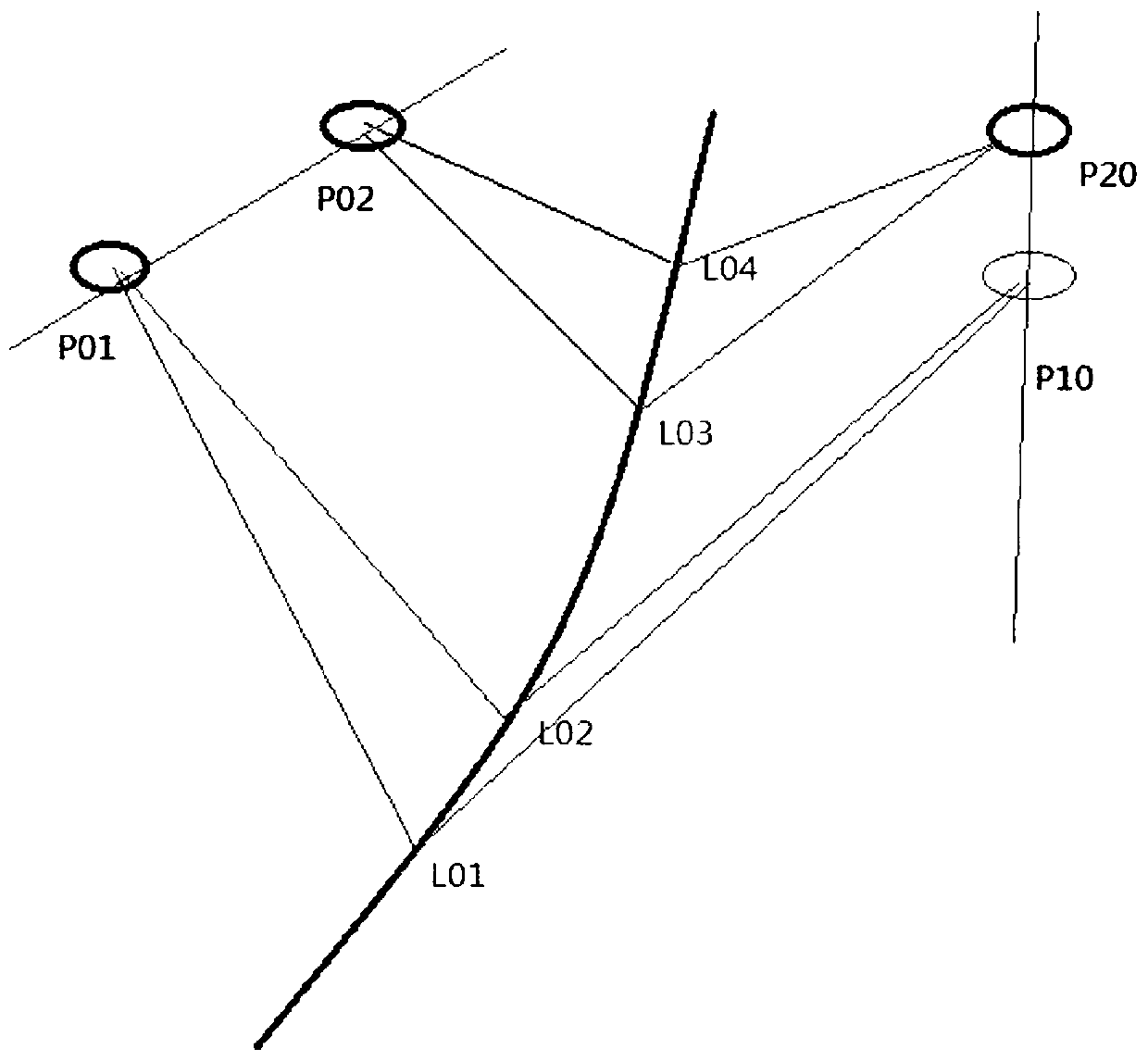
The invention relates to a different-strip-aerial-image-based power sag detection method and system. The system is composed of a calibration selection module, a main control module, a space three-dimensional image pair module, a three-dimensional space model measurement module, and a diagnosis module. The calibration selection module calibrates a flight path and selects a field control point; the main control module controls an unmanned aerial plane to fly according to the flight path and controls the unmanned aerial plane to collect space position information of a photo; the space three-dimensional image pair module establishes a space three-dimensional image pair of a power sag according to the field control point and the space position information of the photo; the three-dimensional space model measurement module identifies a dotted point of the power sag in the space three-dimensional image pair and establishes a three-dimensional space model of the power sag; and the diagnosis module determines a dangerous point on the power sag according to the three-dimensional space model and inputs a detection report automatically. Continuous aerial photos are collected by using the unmanned aerial plane, the identified three-dimensional image queue sequence is constructed in the different strip photos, and space intersection measurement is carried out, thereby completing precise sag measurement of the whole line.

Description

technical field [0001] The invention relates to the technical field of power detection, in particular to a power sag detection method and system based on out-of-band aerial images. Background technique [0002] In the prior art, there are two main methods for measuring power sag: the end-of-gear method for sag observation and laser radar measurement. The end-of-gear method uses theodolite and uses geometric principles to manually measure tangents on the power tower. , to calculate the position and height of the lowest line; the laser radar measurement uses the helicopter to carry out intensive point cloud scanning and vector extraction work, and extracts the spatial position of the electric sag. The above two methods have obvious disadvantages. The sag is observed by the gear end angle method. The manual detection speed is slow and the efficiency is low. It can only measure the lowest sag point. The accuracy is at the meter level. Radar measurement requires expensive equipm...

Claims


Application Information

Patent Timeline
Patent Type & Authority Patents(China)
IPC IPC(8): G05D1/10
CPCG05D1/10
Inventor 张勇龙焕成兵李辉段小祥李娜娜
Owner 航天远景空间地理信息(深圳)有限公司
Learn More